Method of resizing a liquid crystal display

a liquid crystal display and resizing technology, applied in static indicating devices, instruments, non-linear optics, etc., can solve the problems of lcd unusability, lcd damage to the active plate, and many obstacles in resizing an lcd

Inactive Publication Date: 2003-01-21
HONEYWELL INT INC
View PDF14 Cites 43 Cited by
  • Summary
  • Abstract
  • Description
  • Claims
  • Application Information

AI Technical Summary

Problems solved by technology

However, resizing an LCD presents many obstacles due to its construction.
When cutting the display panel 10 by scribing the glass plates, the lower plate (active plate) may be damaged by compressive stress

Method used


Image

  • Method of resizing a liquid crystal display
  • Method of resizing a liquid crystal display
  • Method of resizing a liquid crystal display

Examples


Embodiment Construction

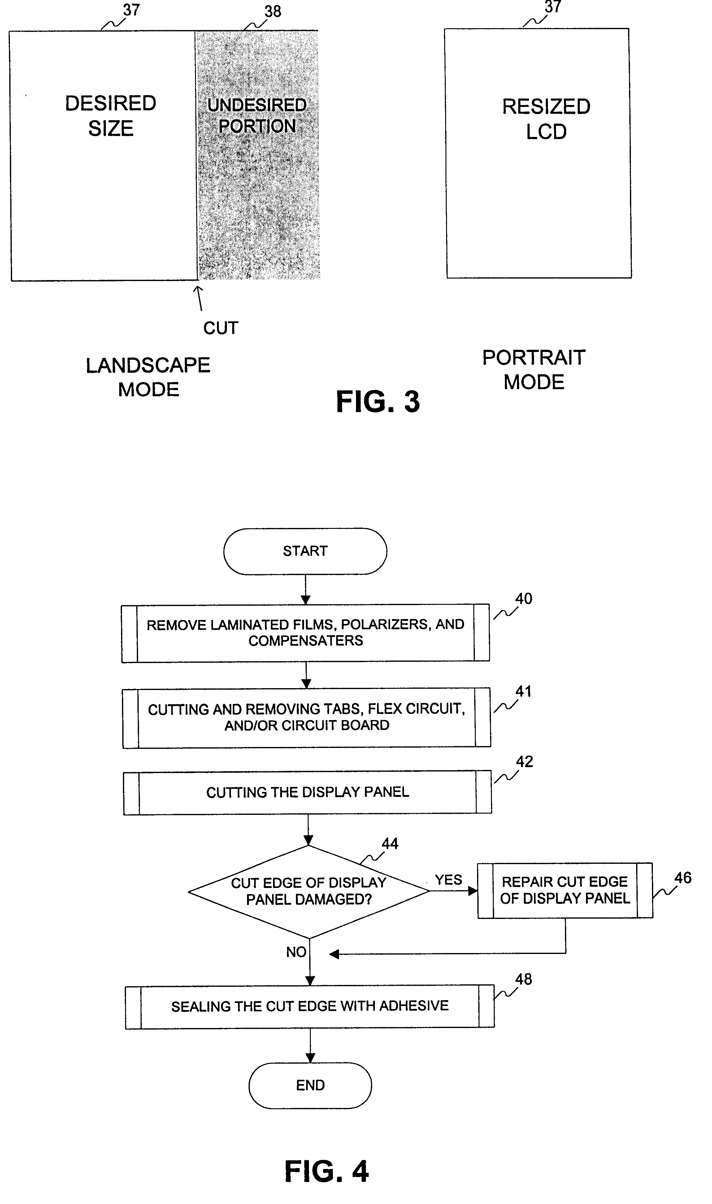
Turning again to the drawings, in which like reference numerals identify similar or identical elements throughout the several views, the present invention provides a method of reducing, or resizing, an oversized LCD to conform to size constraints. Referring again to FIG. 3, an overall size of the LCD is reduced to a desired size 37 by removing an undesired portion 38. In some cases, the aspect (width vs. height) of the LCD may change from landscape (aspect>1) to portrait (aspect<1) or may become square (aspect=1).

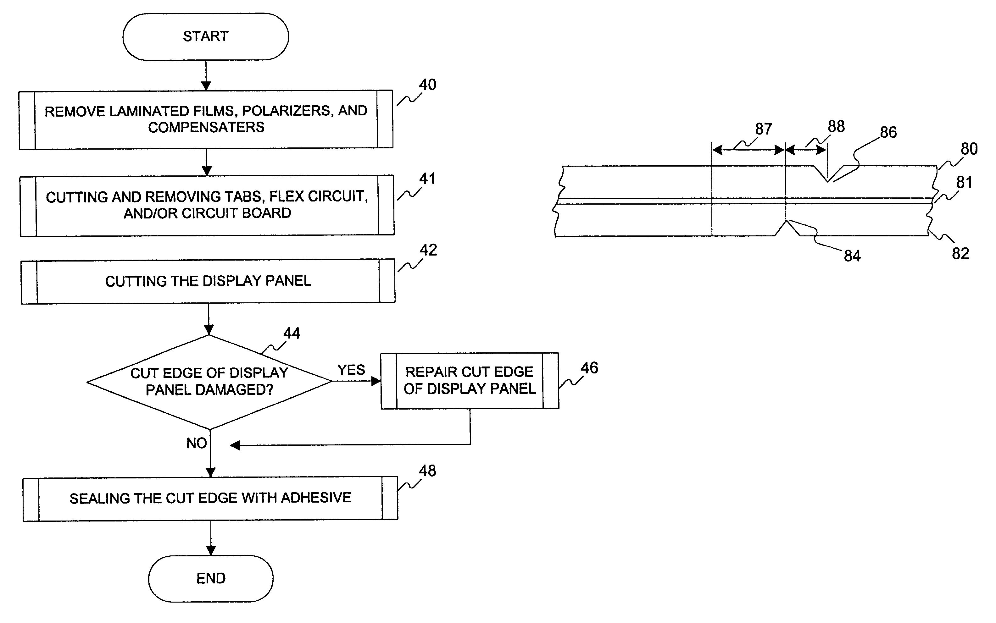
FIG. 4 outlines an overall procedure for resizing an LCD. In Step 40, the polarizer (and compensator) films are removed from the top and bottom substrates in the area to be cut. In step 41, the TABs, flex circuit and / or circuit board are cut and the undesired portions are removed. The display panel is then cut in step 42, and the cut side is examined for damage and resulting gas bubbles. If gas bubbles are detected, the edge is repaired in step 46. The cut edge is then seal...


PUM


Abstract

A method of resizing a liquid crystal display (LCD) includes the steps of first determining a desired size for the LCD, thereby identifying an undesired portion of the LCD. Any tape automated bonding strips (TABs) corresponding to the undesired portions of the LCD are then removed. Any flex circuits, or portion thereof, corresponding to the undesired portion of the LCD are cut and removed. Any circuit boards, or portions thereof, corresponding to the undesired portion of the LCD are cut and removed. The display panel is cut to remove a portion of the display panel corresponding to the undesired portion of the LCD. Finally, the cut edge of the display panel is sealed.

Description

1. Field of the InventionThis invention relates generally to a liquid crystal display (LCD), and more particularly to a method of resizing an LCD.2. Description of the Related ArtLiquid crystal displays (LCD) are well known throughout the art. An active matrix LCD includes row and column address lines and corresponding driving circuitry. This type of display is commonly known as an "X-Y active matrix type LCD." The row and column address lines are typically driven from two to four sides of the LCD. That is, the row address lines are driven from one or two sides of the display and the column address lines are driven from one or two of the remaining sides of the display. In the case that two drivers are used for the row or column address lines, the lines are driven from opposing sides and are interdigitated.The row and column address line driver chips are typically mounted on separate printed circuit boards disposed adjacent to the sides of the display panel and function to interface ...

Claims


Application Information

Patent Timeline
IPC IPC(8): G02F1/13G02F1/1333
CPCG02F1/1333G02F1/133351
Inventor LU, KANGHUASACCOMANNO, ROBERT J.WELCH, RONTHOMPSON, GLEN MERLEMARRON, THOMAS P.
Owner HONEYWELL INT INC
Why Eureka
Try Eureka