Handheld type four-cycle engine

a four-cycle engine, hand-held technology, applied in machine/engine, valve drive, auxillary lubrication, etc., can solve the problems of further increase of the overall height and difficulty in making the engine more compa

Inactive Publication Date: 2003-01-28
HONDA MOTOR CO LTD
View PDF10 Cites 16 Cited by
  • Summary
  • Abstract
  • Description
  • Claims
  • Application Information

AI Technical Summary

Benefits of technology

In accordance with the above-mentioned first characteristic, since the oil tank is provided so as to be connected to one side wall running the length of the crankcase and the cylinder block, it is unnecessary to provide an oil reservoir in the lower part of the crankcase, and the overall height of the engine can thus be reduced and the engine can be made more compact.
Moreover, since the oil mist inside the oil tank is supplied to the crank chamber and the valve operation chamber, and returned to the oil tank by utilising the pressure pulsations of the crank chamber, the inside of the crank chamber and the reciprocating movement section of the valve operation mechanism can be lubricated regardless of the operational position of the engine, and it is unnecessary to employ a special oil pump for circulating the oil mist so simplifying the structure.
In accordance with the above-mentioned second characteristic, since the rotational section of the valve operation chamber functions as part of the oil mist generation means, the oil mist generation means can be obtained in a simple manner.

Problems solved by technology

However, an oil reservoir is formed in the lower part of the crankcase as in the above-mentioned conventional engine, the overall height is further increased and it becomes difficult to make the engine more compact.

Method used


Image

  • Handheld type four-cycle engine
  • Handheld type four-cycle engine
  • Handheld type four-cycle engine

Examples


first embodiment

the present invention shown in FIGS. 1 to 4 is explained first.

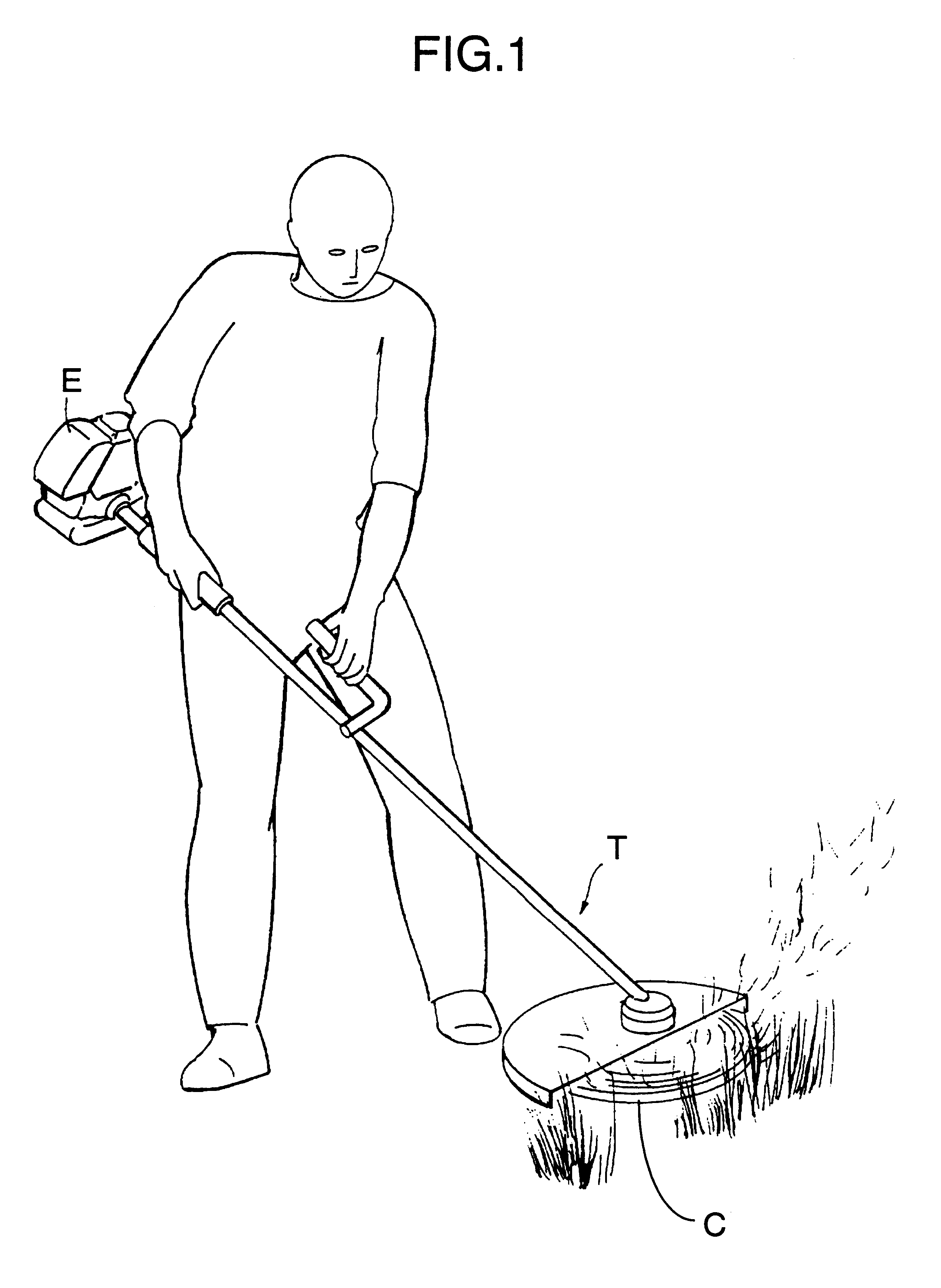
As shown in FIG. 1, a handheld type four-cycle engine E to which the present invention is applied is fitted as the source of power to the drive section of, for example, a powered trimmer T. Since the powered trimmer T is used in a manner in which a cutter C is positioned in various directions according to the operational conditions, the engine E is also tilted to a large extent or turned upside-down as a result and the operational position is unstable.

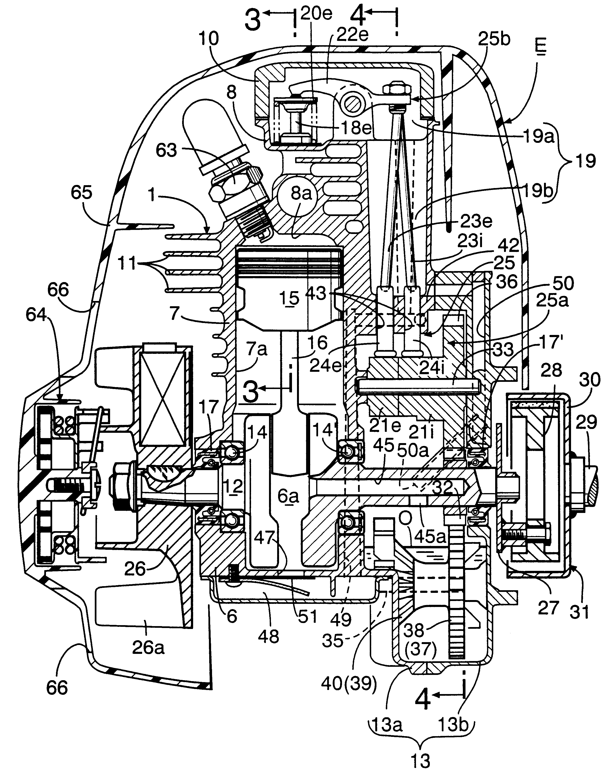
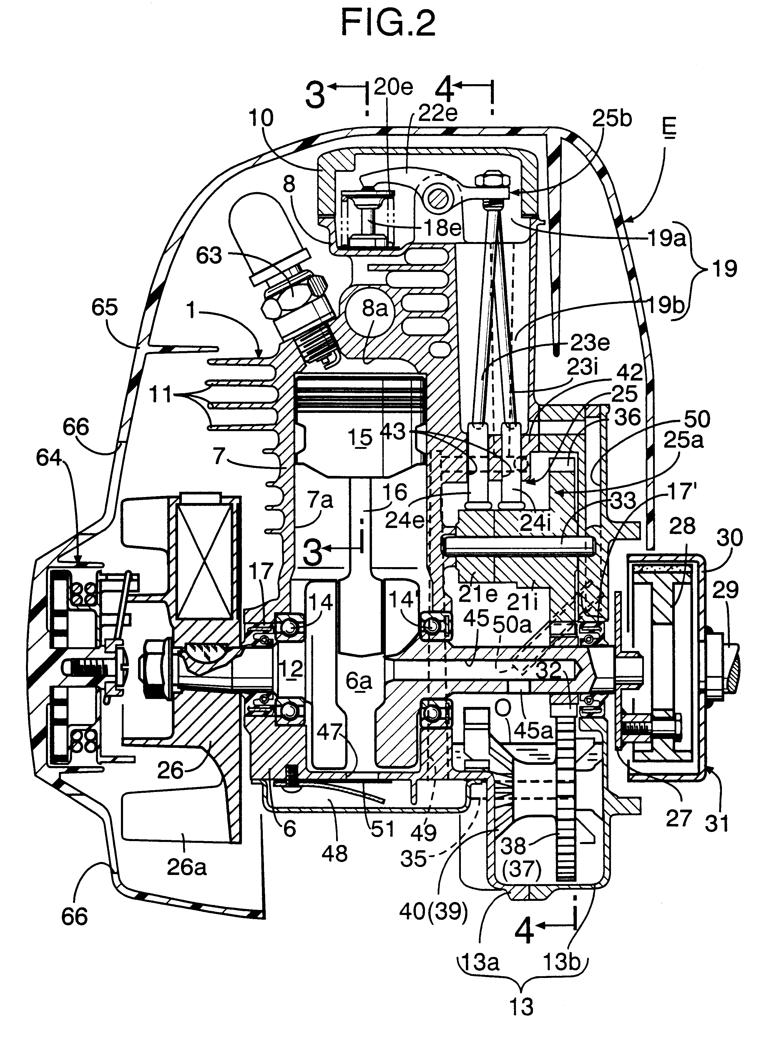
As shown in FIGS. 2 and 3, the engine main body 1 of the above-mentioned handheld type four-cycle engine E includes a crankcase 6 having a crank chamber 6a, a cylinder block 7 having one cylinder bore 7a, and a cylinder head 8 having a combustion chamber 8a, a large number of cooling fins 11 being formed on the outer peripheries of the cylinder block 7 and the cylinder head 8.

A crankshaft 12 housed in the crank chamber 6a is rotatably supported in left and right side walls ...

third embodiments

The second and third embodiments are different from the first embodiment in terms of the arrangement of the toothed oil slingers 37 and 38 around the drive gear 32, the shape of the peripheral wall of the oil tank 13, and the shape and arrangement of the fuel tank 5.

That is to say, in the second embodiment shown in FIG. 5, the two toothed oil slingers 37 and 38 are placed immediately beside and immediately below the drive gear 32 respectively, and the peripheral wall of the oil tank 13 is generally made in the form of a D-shape around the oil slingers 37 and 38 and the cam gear 36, immediately above the drive gear 33. Since there is a comparatively large space outside the vertical wall 13w of the oil tank 13 so formed, a fuel tank 5 having a large capacity can be placed in this space.

In the third embodiment shown in FIG. 6, the two toothed oil slingers 37 and 38 are placed on either side of the drive gear 32 so as to be close to the cam gear 36 placed above the two oil slingers 37 a...


PUM


Abstract

In a handheld type OHV engine, an oil tank is provided so as to be connected to one side wall running the length of a crankcase and a cylinder block, the oil tank houses oil mist generation means to and a rotational movement section of a valve operation mechanism, and the oil mist generated in the oil tank is supplied from a crank chamber to a valve operation chamber of a cylinder head housing a reciprocating movement section of the valve operation mechanism, and is returned to the oil tank by utilizing the pressure pulsations of the crank chamber and a one-way valve. It is thus possible to lubricate the inside of the crank chamber and the valve operation mechanism reliably regardless of the operational position of the handheld type OHV engine while reducing the overall height of the engine.

Description

1. Field of the InventionThe present invention relates to a handheld type four-cycle engine which is mainly used as a power source for portable working apparatus such as a trimmer. More particularly, it relates to improvement of the so-called OHV engine that includes an engine main body, the engine main body including a crankcase having a crank chamber, a cylinder block having a cylinder bore, and a cylinder head having an intake port and an exhaust port; a crankshaft supported in the crankcase and housed inside the crank chamber; a piston fitted in the cylinder bore and connected to the crankshaft; an intake valve and an exhaust valve for opening and closing the intake port and exhaust port, the intake valve and exhaust valve being mounted in the cylinder head; and a valve operation mechanism operable in association with the rotation of the crankshaft so as to open and close the intake valve and exhaust valve.2. Description of the Related ArtAs such an OHV engine which is already k...

Claims


Application Information

Patent Timeline
Patent Type & Authority Patents(United States)
IPC IPC(8): F01M11/00F01M9/00F01M9/06F01M11/06F01M1/00F01M1/04F02B63/02F02B63/00F02B75/02F01L1/02F01M1/06F01M1/16
CPCF01L1/024F01M1/04F01M9/06F02B63/02F01M11/064F02B2275/34F02B2075/027
Inventor ITO, KEITANISHIDA, TAKAOWATANABE, SEI
Owner HONDA MOTOR CO LTD
Why Eureka
Try Eureka