Plastic clipping device

a clipping device and plastic technology, applied in the direction of snap fasteners, buckles, mechanical devices, etc., can solve the problems of clipping devices, reduced grasping force, good to be dropped away,

Inactive Publication Date: 2003-02-11
FIRST CREATE
View PDF20 Cites 55 Cited by
  • Summary
  • Abstract
  • Description
  • Claims
  • Application Information

AI Technical Summary

Benefits of technology

Another object of the present invention, is to provide a sophisticated plastic clipping device comprising less number of the part elements comparing with those of the past one as well as having a difficulty to be in malfunction thereof.
And a separate object of the present invention is to provide a plastic clipping device which can be easily operated only by a single hand of a person.
In order to overcome the above-mentioned problems in the past, since the clipping device of the present invention is so configured that it is comprising a first clamping member, a second clamping member rotatably supported at a part of the first clamping member, an elastically resilient member integrally formed on a part of the first clamping member and for giving the second clamping member a bias force to cause the second clamping member to be moved to a direction whereby the second clamping member moving away from the first clamping member, a coupling piece member integrally formed on a part of the second clamping member, and an operation member rotatably supported on a part of the first clamping member, and wherein the coupling piece member and the operation member being coupled to each other so that a mutual positional relationship between the first and the second clamping members is fixed, it can easily fixedly grasp goods each having various kinds of thickness, respectively.

Problems solved by technology

However, the clipping device of the past has the following problems.
For example, the clipping device such as a clothes-pin, since the clipping force thereof to grasp a good, only depends on a biasing force of a spring per se, when the elasticity thereof is deteriorated, the grasping force thereof also reduced, accordingly, so that it cannot surely grasp a good causing the good to be dropped away.
And further, when a thickness of a good to be grasped is varied, it cannot surely grasp the good and thus when a good having a thickness lower than a predeterminde thickness there would exist a problem in that the good would be fallen out from the clipping device.

Method used


Image

  • Plastic clipping device
  • Plastic clipping device
  • Plastic clipping device

Examples


Embodiment Construction

A specific embodiment of a clipping device of the present invention will be explained with reference to the attached drawings, hereunder.

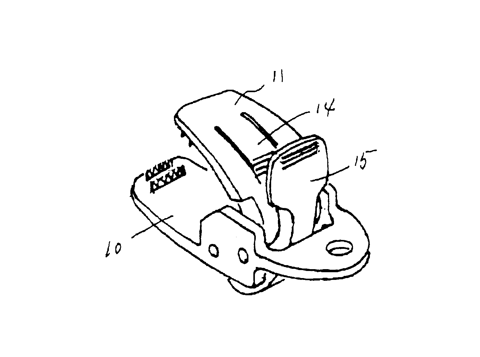
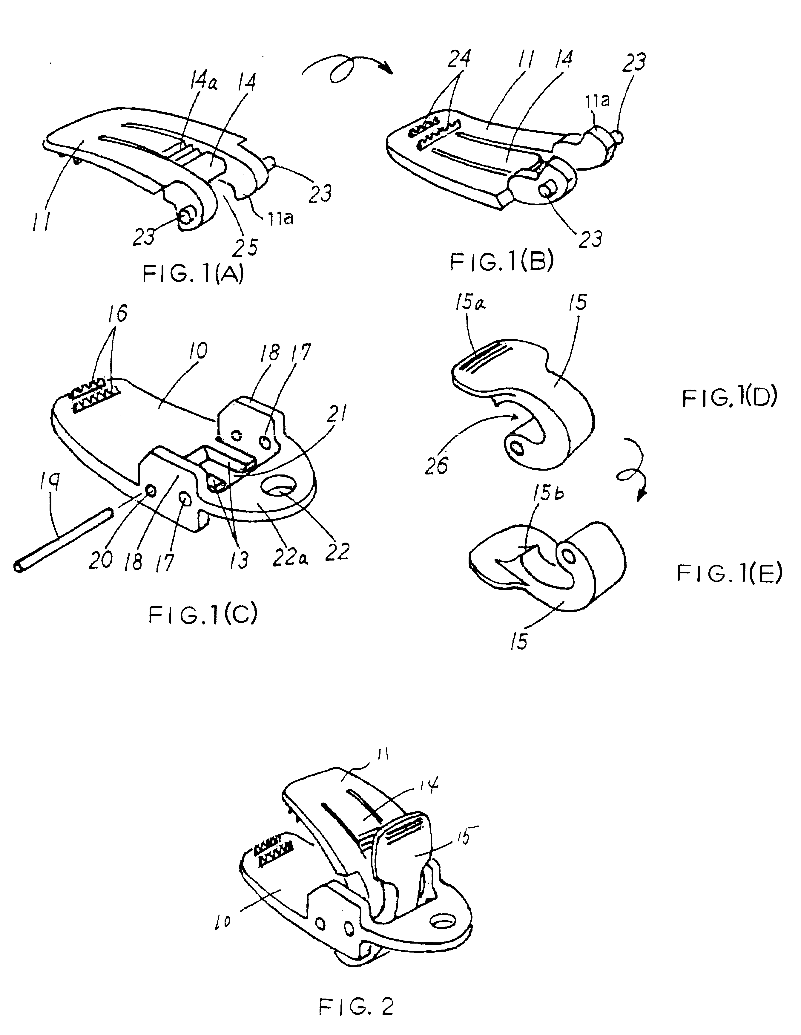
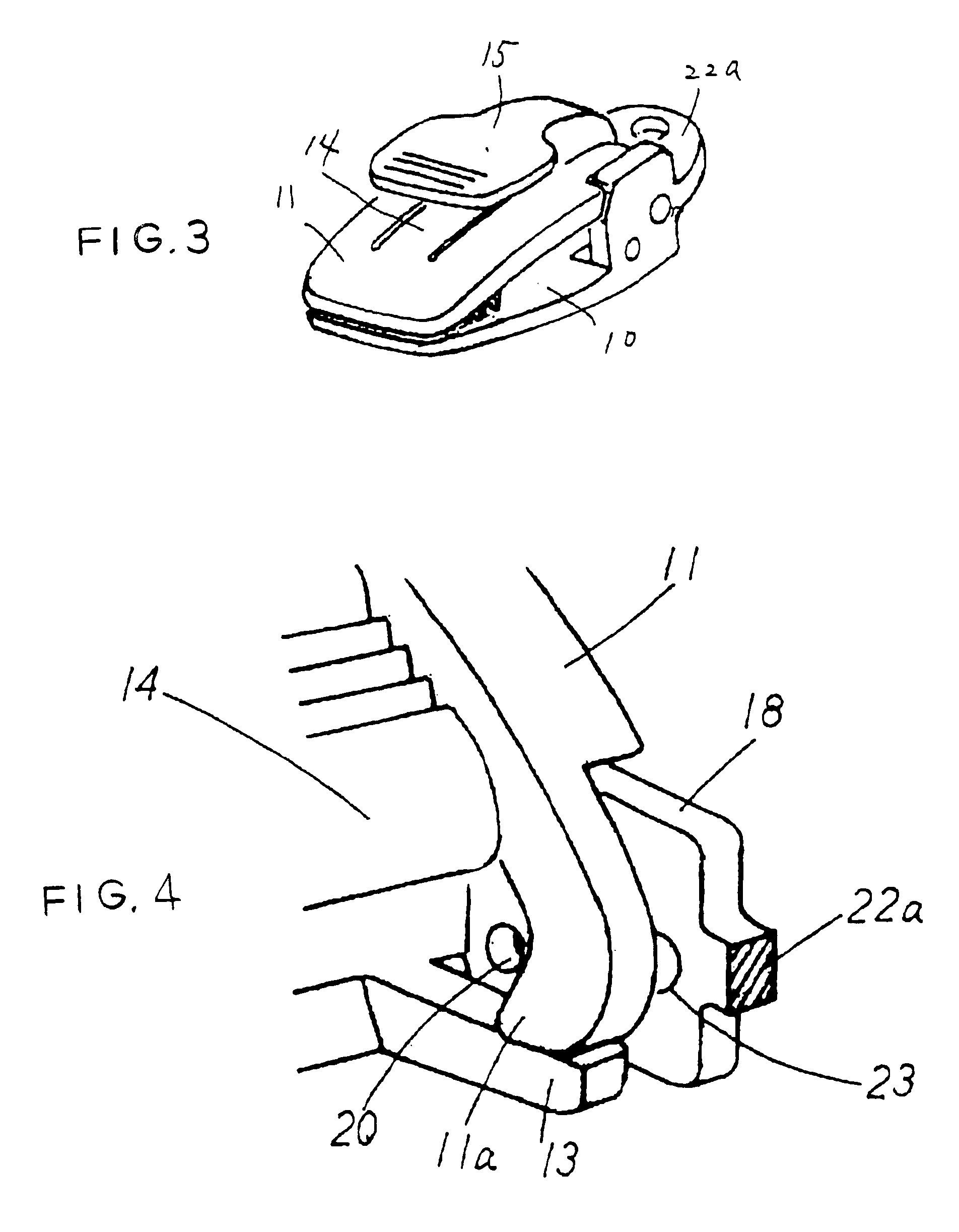
As mentioned above, FIGS. 1(A) to (E) are perspective views of the respective part elements separated from one embodiment of a clipping device of the present invention, respectively, and FIG. 2 is a perspective view of a completely assembled clipping device of one embodiment of the present invention and which shows a condition in that the clamping elements thereof being opened while FIG. 3 is a perspective view of a completely assembled clipping device of one embodiment of the present invention and which shows a condition in that the clamping elements thereof being closed.

As apparent from these drawings, the clipping device of the present invention comprises a first clamping member 10, a second clamping member 11 rotatably supported at a part of the first clamping member 10, an elastically resilient member 13 integrally formed on a part of the firs...


PUM


Abstract

The present invention is to provide a clipping device made of plastic and which can surely grasp any good regardless a thickness thereof and which comprises a first clamping member 10, a second clamping member 11 rotatably supported at a part of the first clamping member 10, an elastically resilient member 13 integrally formed on a part of the first clamping member 10 and giving the second clamping member 11 a bias force to cause the second clamping member 11 to be moved to a direction whereby the second clamping member 11 to be opened, a coupling piece member 14 integrally formed on a part of the second clamping member 11, and an operation member 15 rotatably supported on a part of the first clamping member 10, and in that by coupling the coupling piece member with the operation member, the first and the second clamping members are fixed to each other.

Description

BACK GROUND OF THE INVENTION1. Field of the InventionThe present invention relates to a clipping device which can clamp things, especially relates to a plastic clipping device which, for example, is a clipping device for binding a plurality of documents together or a grasping device for surely grasping an object good therewith and for holding it when it is used for as a strap of a movable telephone or of a skiing cap whereby a user being prevented from loosing same.2. Description of the Related ArtsGenerally speaking, a clipping device having a pair of clipping elements made of plastic, metal, wood or the like, which are biased to a direction to make a clamping utilizing a metallic spring or the like, for example, a clothes-pin.On the other hand, in a separate embodiment of the past, it has been proposed that a clipping device made of an elastic thin plate and having a cross-sectional configuration of being an U-shaped form and an opening portion thereof being caused to be deformed ...

Claims


Application Information

Patent Timeline
Patent Type & Authority Patents(United States)
IPC IPC(8): A44B21/00A44B99/00B42F1/02B42F1/10D06F55/00D06F55/02F16B2/18
CPCA41F11/06A44B99/00Y10T24/44521Y10T24/4745Y10T24/44376Y10T24/44419F16B2/20
Inventor OGINO, NOBUAKISANO, KOICHI
Owner FIRST CREATE
Why Eureka
Try Eureka