Method of breathing tracheally

a tracheal humidification and tracheal tube technology, applied in the field of tracheal humidification system improvement, can solve the problems of increased patient care costs, inability to overcome hereditary drawbacks, and patient exposure to airborne and contact sources, so as to increase resistance and make breathing difficul

Inactive Publication Date: 2003-02-11
DAVIES TIMOTHY A
View PDF8 Cites 57 Cited by
  • Summary
  • Abstract
  • Description
  • Claims
  • Application Information

AI Technical Summary

Benefits of technology

The present invention is directed to an improved tracheal humidification system which overcomes the disadvantages of the prior art. A preferred name for the present invention is the "Safe and Silent" Waterless System. In the present invention the HCH or HME filter is removed from the path of secretions. That is, the breathing and secretion paths or passages are different. By removing the filter from the path of secretions, the filters now perform as designed, capturing humidity and warmth while staying free of secretions that increase resistance and make breathing difficult. The patient breathes through a closed system, exhaling through the HCH or HME filter, which captures the patient's own heat and humidity. The patient then inhales and the entrained air recaptures the moisture and heat. The present invention also provides minimal deadspace and maximal drain for expelled secretions.

Problems solved by technology

While this time-tested method of providing humidification worked, it has inherent drawbacks that could not be overcome.
Current aerosols require high-flow oxygen and greatly increase the cost of caring for the patient.
This is labor-intensive.
The open nature of the tracheal aerosol leaves the patient susceptible to infection by airborne and contact sources.
Current aerosols are noisy, and high noise levels do not provide for a good environment of care.
Secretions are expelled and tend to collect around the trachea, soiling linen, tracheal dressings etc., and increasing nursing time at the bedside and the overall cost of care.
These systems have been used on mechanically ventilated patients with great success by using the patients' own humidity and moisture but have been used only rarely on naturally ventilated patients due to their tendency to clog with secretions (refer to FIG. 1).
However, these systems 500 are troublesome in that the high volume of secretions associated with a tracheotomy clog the filter 502 thereby making breathing difficult.

Method used


Image

  • Method of breathing tracheally
  • Method of breathing tracheally
  • Method of breathing tracheally

Examples


Embodiment Construction

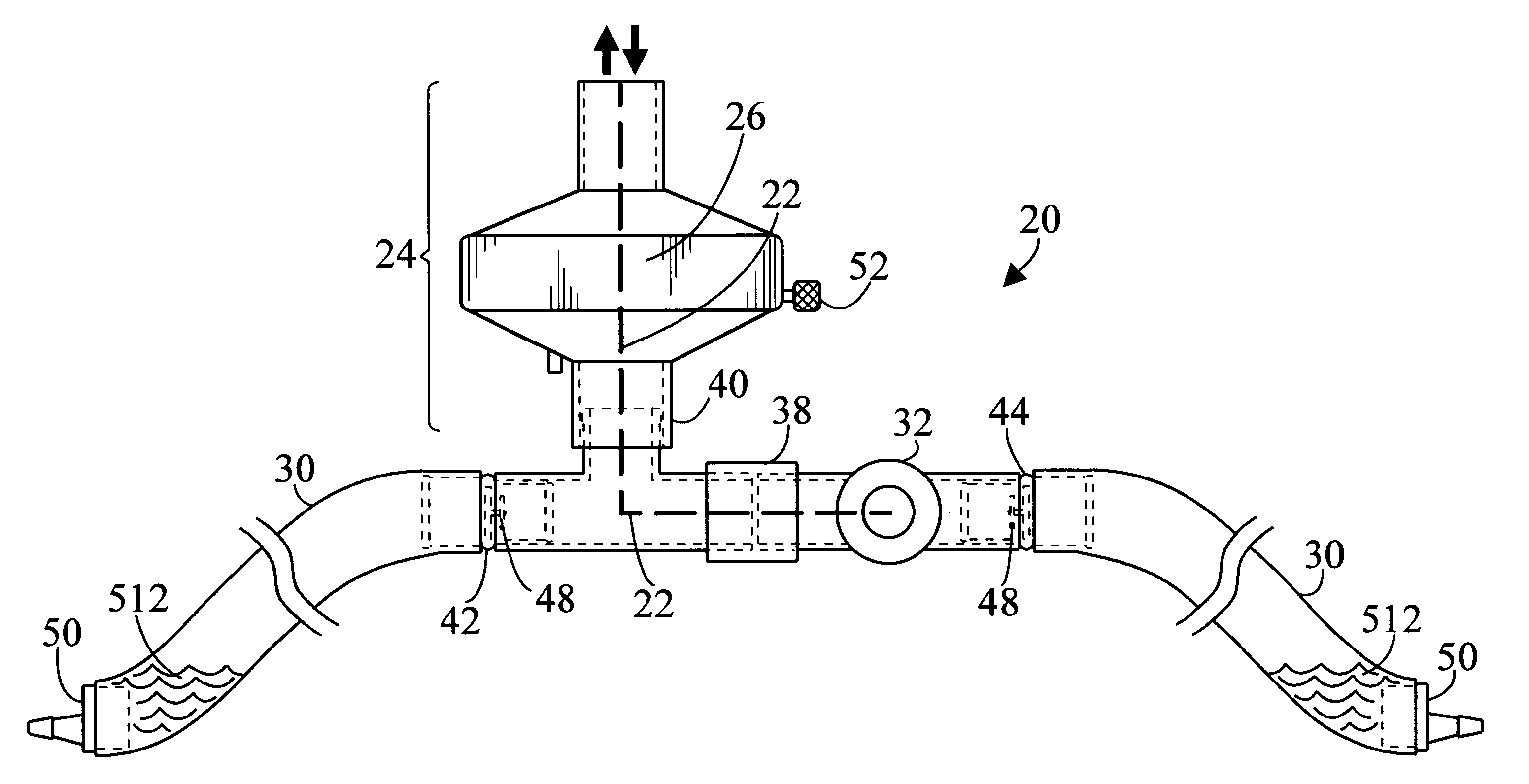
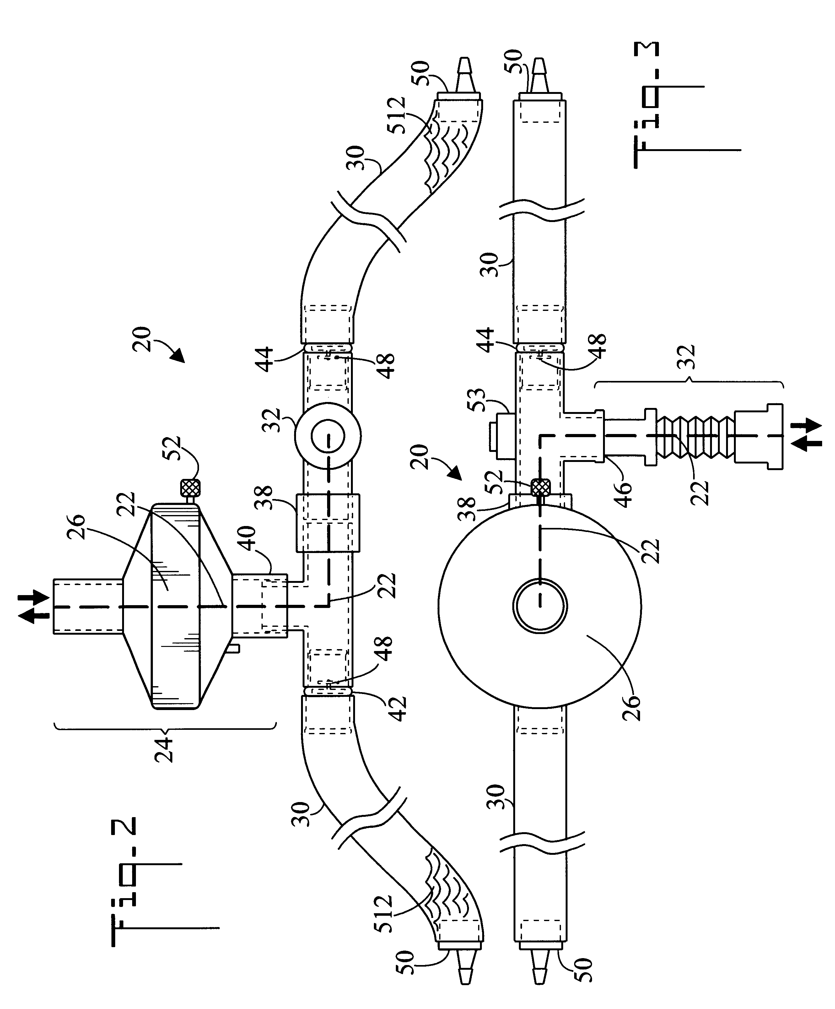
Referring initially to FIGS. 2-4, and 8, there are illustrated side elevation, top plan, end elevation, and reduced perspective views respectfully of a tracheal humidification system in accordance with the present invention, generally designated as 20. Tracheal humidification system 20 includes a breathing path 22 (shown by a heavy dashed line) having an uppermost portion 24 which is oriented in a substantially vertical position. The patient breathes in and out through breathing path 22. The uppermost portion 24 includes a filter 26 and filter housing. The tracheal humidification system 20 also includes at least one secretion path 28 (shown in a heavy dotted line in FIGS. 5-7). In a preferred embodiment two bilateral secretion paths 28 are utilized which include two flexible drain tubes 30. The flexible drain tube portion 30 of the secretion path 28 is downwardly oriented so as to collect and capture the secretions 512. In the shown in use configuration, filter 26 is disposed above ...


PUM


Abstract

A tracheal humidification system (20) includes a filter (26) for humidifying the air being breathed by the patient. The filter (26) is disposed in an uppermost portion (24) of a breathing path (22). At least one secretion path (28) including a drain tube (30) is provided for collecting secretions (512) from the patient. Filter (26) is disposed above the secretion path (28), so that the secretions (512) are prevented from contacting and clogging filter (26).

Description

The present invention pertains generally to tracheal surgery or tracheotomy, and in particular to an improved tracheal humidification system. The system of the present invention employs different breathing and secretion paths, and further elevates the breathing filter so that it cannot be contaminated by secretions.After having a tracheotomy, a patient is fitted with a ventilator system to facilitate healing and recovery. One of the functions of the ventilator system is to trap bronchial secretions. Another feature of the ventilator system is to humidify the air that the patient breaths to reduce drying of the mucus. For years the ventilator systems injected aerosolized water which was directed at the trachea. While this time-tested method of providing humidification worked, it has inherent drawbacks that could not be overcome. Some of drawbacks are:Current aerosols require high-flow oxygen and greatly increase the cost of caring for the patient.Tubing must be constantly drained to ...

Claims


Application Information

Patent Timeline
Patent Type & Authority Patents(United States)
IPC IPC(8): A61M16/04
CPCA61M16/047
Inventor DAVIES, TIMOTHY A.
Owner DAVIES TIMOTHY A
Why Eureka
Try Eureka