Fluid-powered energy conversion device

a technology of flue-powered energy and conversion device, which is applied in the direction of electric generator control, renewable energy generation, greenhouse gas reduction, etc., can solve the problems of large permanent environmental changes, large cost, and large size of wind-powered devices, and achieves large-scale environmental protection and environmental protection. the effect of reducing the number of wind-powered devices

Inactive Publication Date: 2003-02-11
MCDAVID JR WILLIAM K
View PDF28 Cites 90 Cited by
  • Summary
  • Abstract
  • Description
  • Claims
  • Application Information

AI Technical Summary

Benefits of technology

The floor of the upstream annular chamber slopes in a downstream direction as it approaches a central longitudinal axis of the device, thereby causing the drive vortex to flow downstream and pass through a central aperture located between the upstream annular chamber and the downstream annular chamber. The turbine is centrally mounted on a longitudinal drive shaft in the central aperture. The turbine is rotated by the drive vortex as the drive vortex passes through the turbine and combines with the extraction vortex, increasing its downstream velocity.
In yet another aspect, the present invention is a fluid-filled flywheel mounted on a drive shaft for reducing start-up inertia of the flywheel and maintaining angular momentum of the drive shaft as it rotates in a direction of rotation. The fluid-filled flywheel includes a hollow disk-shaped shell filled with fluid, and a plurality of radial bulkheads that separate the interior of the shell into separate sections. Each of the radial bulkheads includes at least one gate pivotally mounted thereon to open in a direction opposite to the direction of rotation. Each gate covers an aperture in the bulkhead when the gate is pivoted to a closed position, and each gate opens the aperture when the gate is pivoted to an open position. When the flywheel accelerates in the direction of rotation, the gates are opened by the fluid thus allowing the fluid to flow through the apertures in the bulkheads and reduce the start-up inertia of the flywheel. When the flywheel decelerates, the gates are closed by the fluid thus preventing the fluid from flowing through the apertures, and causing the flywheel to maintain angular momentum like a solid flywheel. The fluid-filled flywheel is particularly efficient when utilized with a wind-powered energy conversion device for which the input energy level varies.

Problems solved by technology

However, this requires major permanent environmental changes to the areas where dams are built and reservoirs rise.
This is particularly true for sources that are non-polluting and inexhaustible.
Wind-powered devices, in particular, are expensive, inefficient, dangerous, noisy, and unpleasant to be around.
To capture a large volume of wind, existing wind-powered devices are very large.
As a result, they cannot be distributed throughout population centers, but must be installed some distance away.
Then, like dams with hydro-electric generators, the electrical energy they generate must be transmitted, at considerable cost and with considerable lost energy, to the population centers where the energy is needed.
However, with existing technology, smaller units suitable for distributing throughout a population area are not efficient enough to provide a sufficient amount of energy to power a structure such as a house or office building.
In addition, such units are visually obtrusive and noisy, making them unsuitable for use in residential or other highly populated settings.
This is an inefficient design because energy is extracted from the wind by reducing the wind velocity as it passes through the propeller.
The use of such massive blades, however, has its own disadvantages.
First, the propellers are known to kill or injure thousands of large birds each year.
Second, the massive blades can be dangerous if the device fails structurally and the propeller breaks loose.
In this case, the propeller can fly a considerable distance and cause serious damage or injury to anything or anyone in its path.
Third, the propeller design contains an inherent gravitational imbalance.
This imbalance creates a great deal of vibration and stress on the device.
At great expense, consequently, the device must be structurally enhanced to withstand the vibration and stress, and thus avoid frequent maintenance and / or replacement.

Method used


Image

  • Fluid-powered energy conversion device
  • Fluid-powered energy conversion device
  • Fluid-powered energy conversion device

Examples


Embodiment Construction

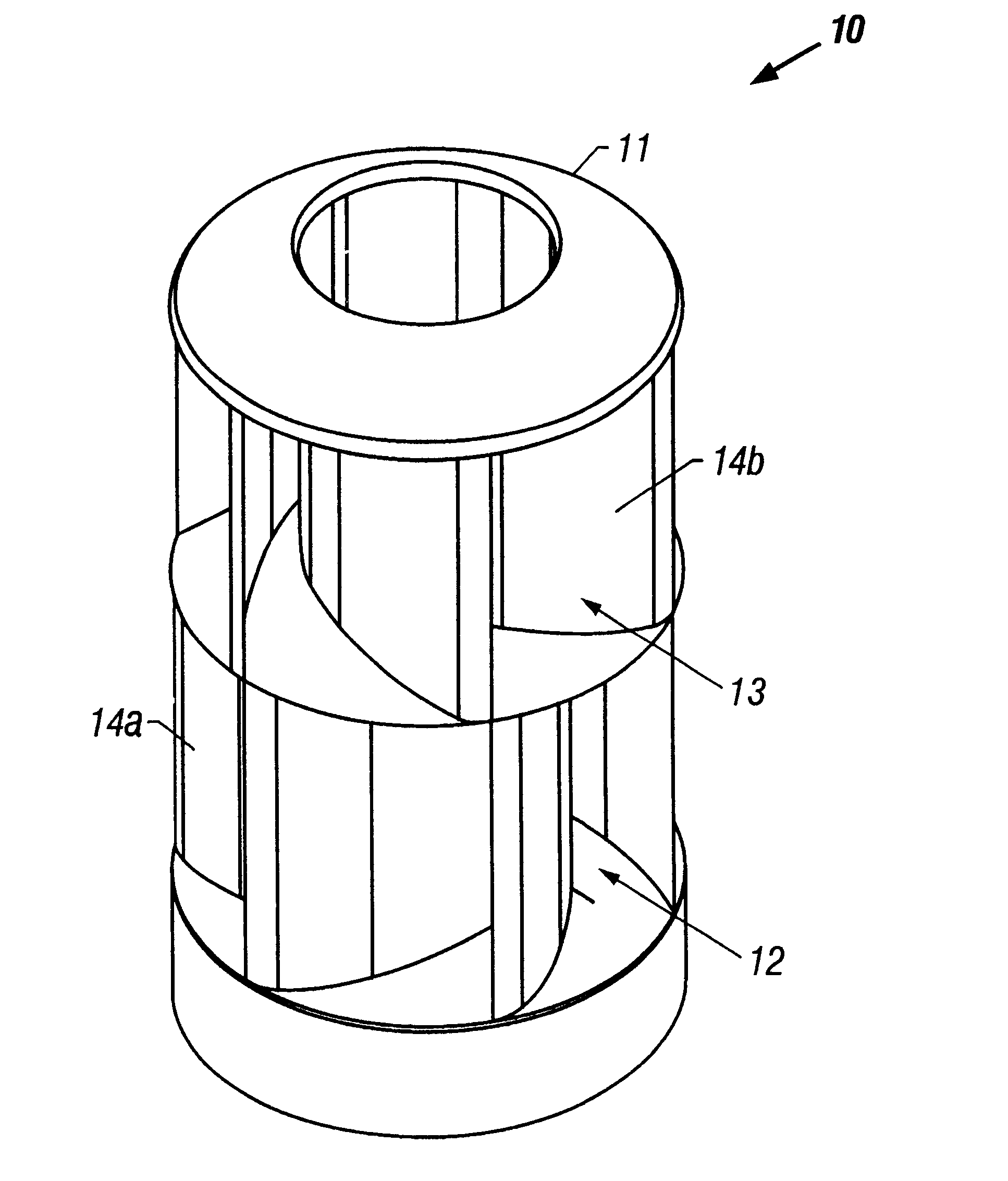
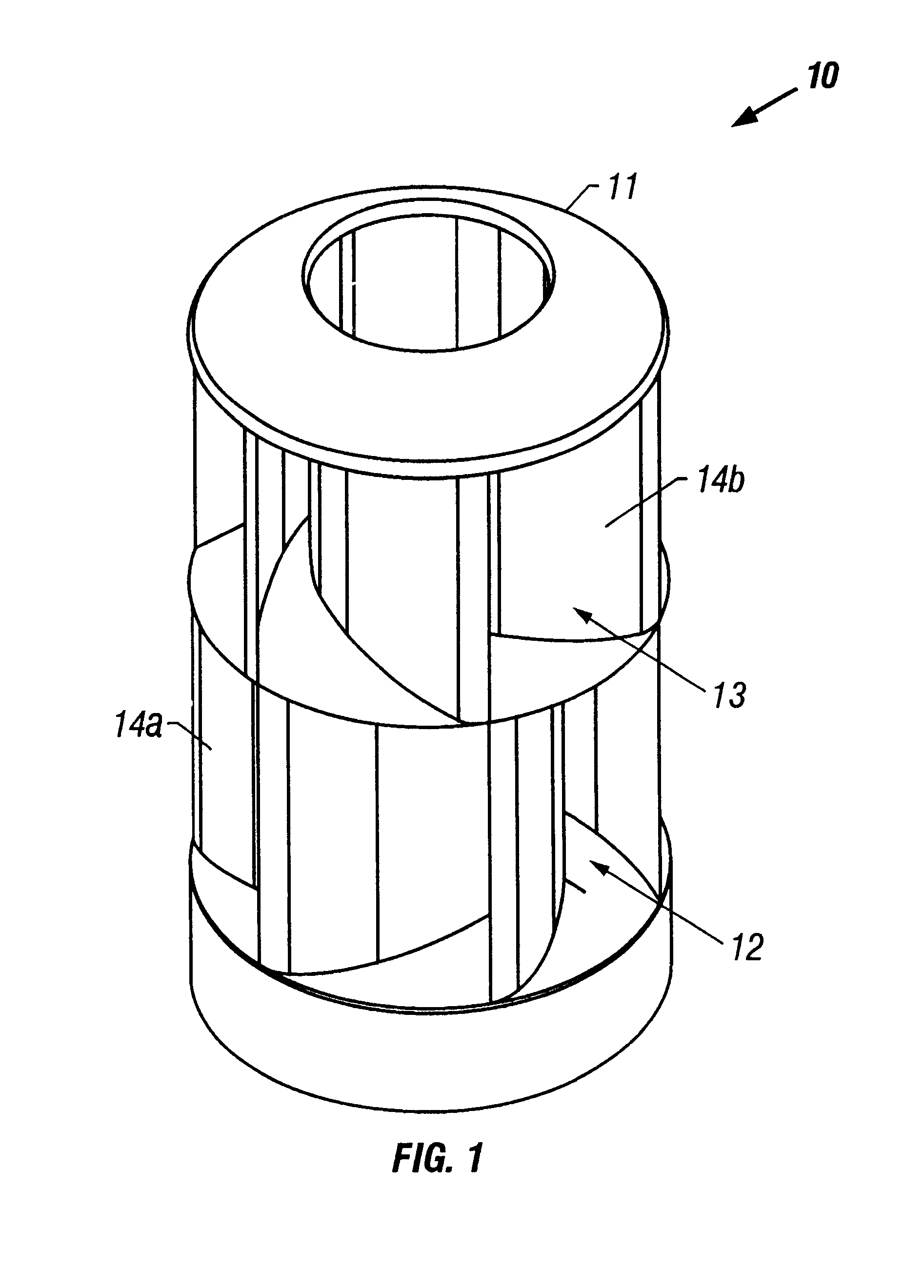
FIG. 1 is a perspective view of an embodiment of the present invention that converts wind energy to mechanical or electrical energy. The energy conversion device 10 includes a stationary cowling 11 surrounding an upstream annular chamber 12 and a downstream annular chamber 13. The cowling may be constructed of any suitable rigid material such as wood, plastic, metal, and so on. Furthermore, the cowling may be fabricated from a transparent material, making the device visually unobtrusive. In the preferred embodiment of the present invention, the cowling is cylindrical and is constructed of a high-grade, ultraviolet-protected plastic.

The cowling 11 includes a plurality of longitudinal baffles that are curved and arranged in a toroidal pattern. Upstream baffles 14a are mounted in the upstream annular chamber 12, and downstream baffles 14b are mounted in the downstream annular chamber 13. In the preferred embodiment of the present invention, approximately six toroidal longitudinal baffl...


PUM


Abstract

A fluid-powered energy conversion device for converting energy in a moving fluid such as air into mechanical energy. A rigid cylindrical frame includes an upstream annular chamber and a downstream annular chamber, each of the chambers having sides that are open to allow entry of the wind. A plurality of longitudinal baffles form a toroidal pattern that creates an upstream drive vortex in the upstream chamber, and a downstream extraction vortex rotating in the opposite direction in the downstream chamber. The drive vortex rises and changes direction as it passes through a turbine mounted on a longitudinal drive shaft in a central aperture between the chambers. The turbine is rotated by the rotational momentum of the drive vortex, by lift that is generated by each turbine blade, and by additional momentum that is created by the vortex reversal.

Description

1. Technical Field of the InventionThe present invention relates generally to electrical generation and energy conversion devices, and more particularly to a fluid-powered energy conversion device that converts the energy of wind or flowing water to mechanical or electrical energy.2. Description of Related ArtThe use of wind or flowing water to provide power for various uses dates back many centuries. In modern times, wind and water have been used to generate electricity. Hydro-electric generating plants have been used to generate large quantities of electrical energy for widespread distribution. However, this requires major permanent environmental changes to the areas where dams are built and reservoirs rise. Wind-powered devices, in general, have been used to perform mechanical work, or to generate electricity, only on a limited scale. With the ever increasing demand for additional or alternative energy sources, all possible sources are being given more scrutiny. This is particula...

Claims


Application Information

Patent Timeline
Patent Type & Authority Patents(United States)
IPC IPC(8): F04D1/04F04D1/00F03D1/00F03D1/04
CPCF03D1/04F04D1/04Y02E10/72F05B2240/132Y02E60/16Y02E10/74F03D9/12F03D3/0409Y02E70/30
Inventor MCDAVID, JR., WILLIAM K.
Owner MCDAVID JR WILLIAM K
Why Eureka
Try Eureka