Surveillance tag applicator

a technology of applicators and tags, applied in the direction of mechanical control devices, instruments, process and machine control, etc., can solve the problems of compromising the speed and accuracy of the mechanism cannot handle box blanks coming, and the difficulty of transferring "tags" with adhesive backing to target articles within the required specifications, etc., to achieve the effect of high speed

Inactive Publication Date: 2003-03-04
SHRINK PACKAGING SYST
View PDF19 Cites 22 Cited by
  • Summary
  • Abstract
  • Description
  • Claims
  • Application Information

AI Technical Summary

Problems solved by technology

Transferring "tags" with an adhesive backing from a storage material (such as mylar or other similar materials) to a target article within required specifications is extremely difficult, particularly when the target material is moving at high rates of speed.
The stamps are picked up by the stamp-carrying pads of the wheel by the contact between web and these pads, which contact occurs at a point B. However, problems occur when the product is not evenly spaced on the conveyor.
"Tag" speeds and accuracy may be compromised.
Also, this mechanism cannot handle box blanks coming at random spacing between blanks, and it cannot be rotated to put labels on at right angles to the direction of labels coming off a carrier web.
However, the speed of this machine is not fast enough for the requirements of the industry.
The vacuum may not hold the pitch on the drum at higher stop-and-start speeds, and this labeling machine cannot handle randomly spaced items coming to the labeler.
However, this machine relies on a continuous motion of the web and the product at preset spacing.
However, the constant speed of this machine does not conform to the current standard of the industry.
Also, the tape strips cannot be pressure applied at high speeds without skewing the tape strips or moving individual envelopes.
However, this is also a continuous motion machine with speeds far too slow for the current industry requirements.

Method used


Image

  • Surveillance tag applicator
  • Surveillance tag applicator
  • Surveillance tag applicator

Examples


Embodiment Construction

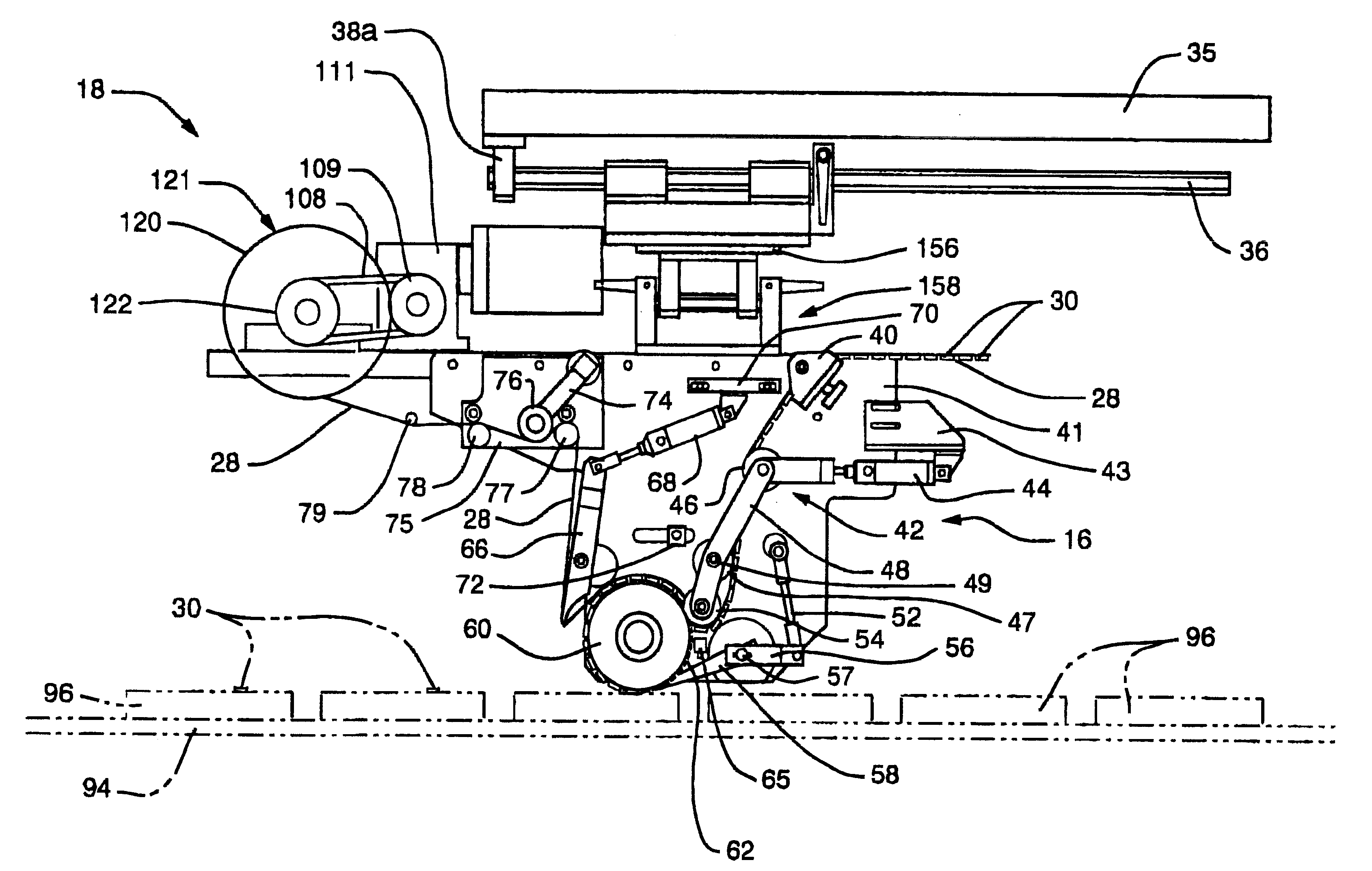
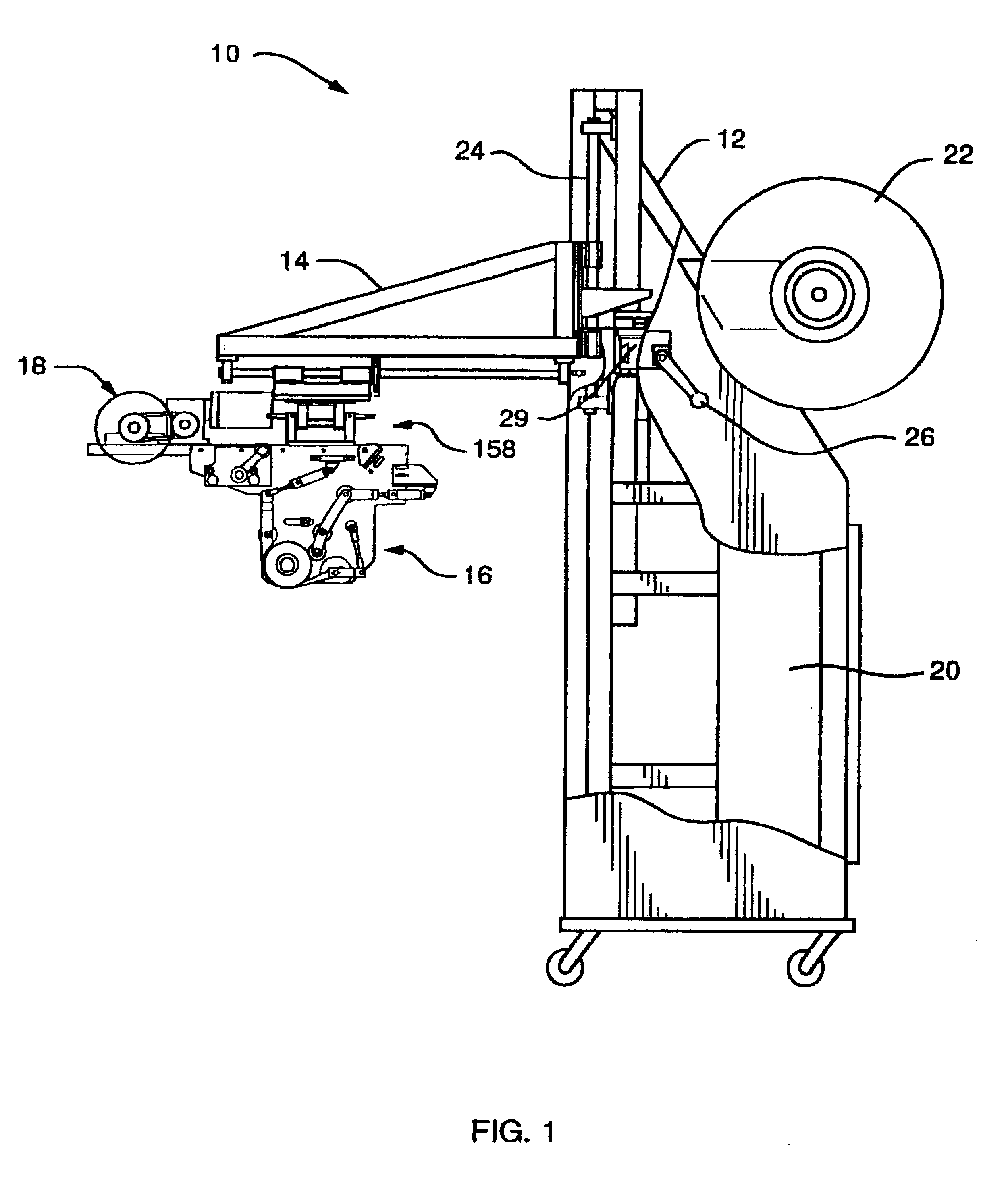
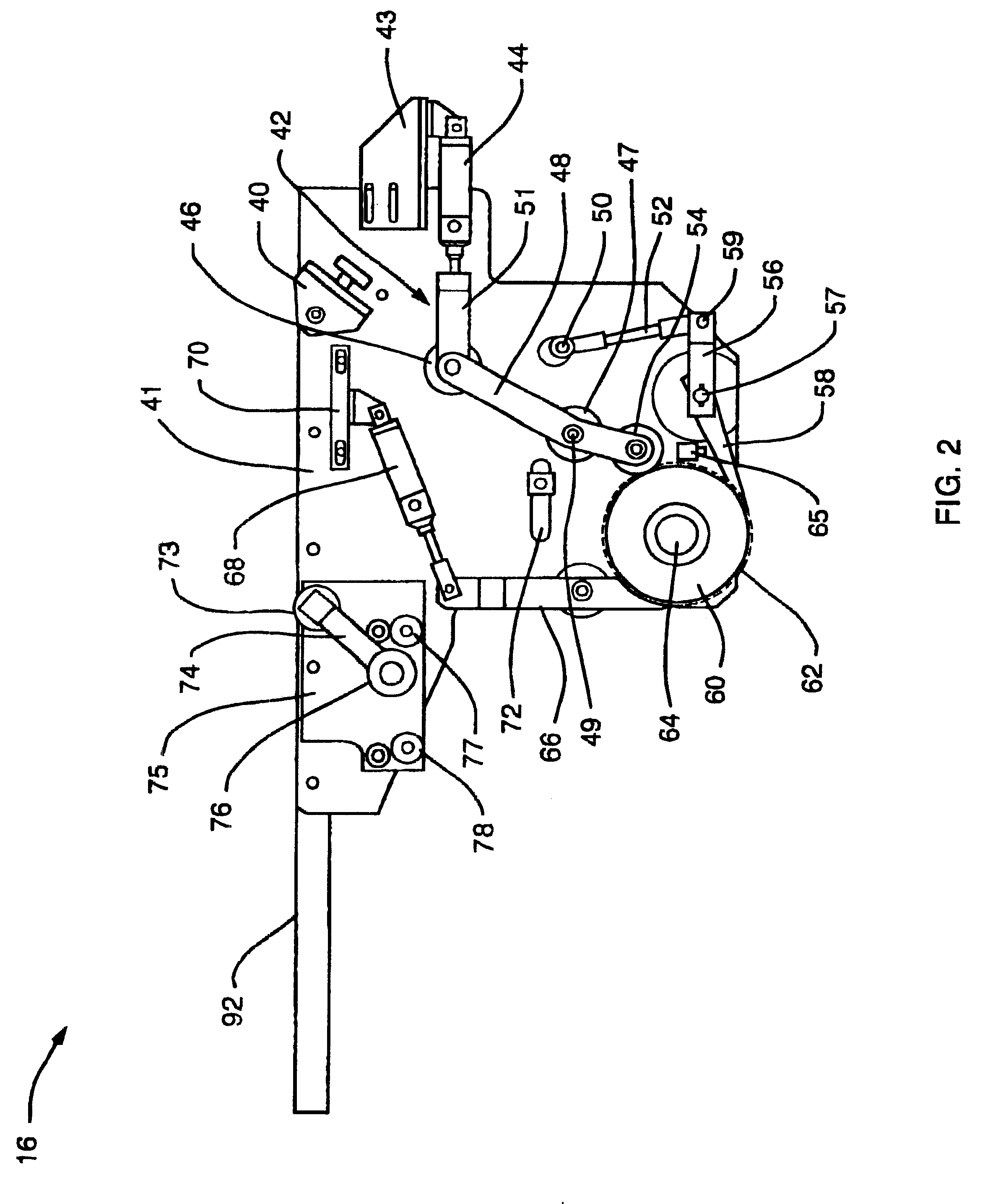
Referring to FIG. 1, a side elevational view of the invention of a surveillance tag applicator 10 is shown comprising a frame assembly 12, an adjustable frame assembly 14, an applicator assembly 16 and a rewind assembly 18. Also located within the main frame assembly 12 is a programmable controller 20 for controlling the operation of the surveillance tag applicator 10.

High Speed Tag Applicator

Still referring to FIG. 1 and also FIG. 7, FIG. 7 shows an elevational view of the applicator assembly 16 and the rewind assembly 18 with a web 28 of tags 30 threaded through the assemblies 16, 18 for application of the tags 30 to articles 96 passing by a drum 60 on a conveyor 94. The tags 30 are attached to the web 28 with an adhesive which enables attachment of the tags 30 to the articles 96. As best seen in FIG. 7, the surveillance tag applicator 10 applies surveillance tags 30 such as Electronic Article Surveillance (EAS) tags to articles 96 such as box blanks, blister cards, packages, boxe...


PUM

PropertyMeasurementUnit
angleaaaaaaaaaa
widthaaaaaaaaaa
widthaaaaaaaaaa

Abstract

A surveillance tag applicator for applying tags to articles such as box blanks, blister cards, or containers at very high rates of speed up to and greater than 1000 tags per minute. The applicator comprises a plurality of tags attached to a web fed to a rotating drum having a plurality of slots, a compression roller for pressing each of the tags into one of the plurality of slots, an ejector arm for ejecting each tag from the slots onto a selected location of an article passing by the drum, a stripper to remove the web from the tags, and a winder assembly for rewinding the web devoid of tags. A first servo motor drives the rotating drum and a second servo motor drives the ejector arm. A controller provides the timing and control for the servo motors and operation of the tag applicator.

Description

The present invention relates generally to an apparatus and method for transferring tags to articles such as box blanks, blister cards, boxes or other containers, and in particular to a very high speed surveillance tag applicator apparatus having an indexed rotating drum with a plurality of slots around the circumference of the drum for receiving surveillance tags and then transferring the tags onto the articles either perpendicular to or parallel to the direction of travel of the moving articles.DESCRIPTION OF RELATED ARTTransferring "tags" with an adhesive backing from a storage material (such as mylar or other similar materials) to a target article within required specifications is extremely difficult, particularly when the target material is moving at high rates of speed. The current average speed to apply "tags" is about 200 to 300 per minute. Speeds required by the industry are now 1000 tags per minute or greater.U.S. Pat. No. 2,621,434, issued Dec. 16, 1952 to E. W. Jackson e...

Claims


Application Information

Patent Timeline
Patent Type & Authority Patents(United States)
IPC IPC(8): B65C1/00B65C1/02B65C9/08B65C9/18B65C9/00B65C9/42
CPCB65C1/021B65C9/1865B65C9/42Y10T156/1771Y10T156/1768
Inventor WILLIAMS, EDWARD F.JAMES, FRANK A.LINDBERG, JEFFREY C.
Owner SHRINK PACKAGING SYST
Why Eureka
Try Eureka