Power management strategy to support hot swapping of system blades during run time

a power management strategy and blade technology, applied in the direction of switches, cables, instruments, etc., can solve problems such as power managemen

Inactive Publication Date: 2003-03-04
INTEL CORP
View PDF4 Cites 48 Cited by
  • Summary
  • Abstract
  • Description
  • Claims
  • Application Information

AI Technical Summary

Problems solved by technology

One of the major problems in these systems is

Method used


Image

  • Power management strategy to support hot swapping of system blades during run time
  • Power management strategy to support hot swapping of system blades during run time
  • Power management strategy to support hot swapping of system blades during run time

Examples


Embodiment Construction

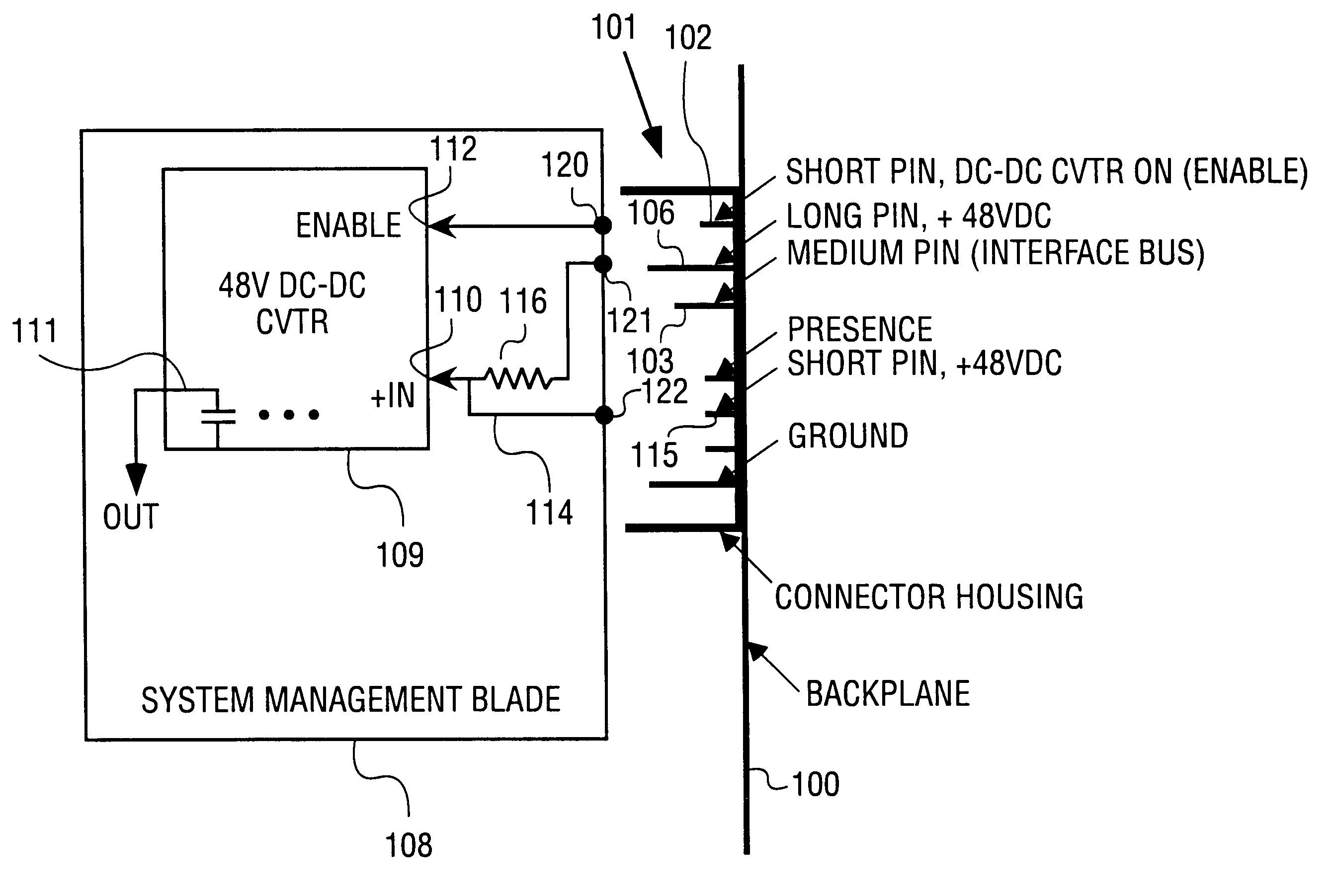
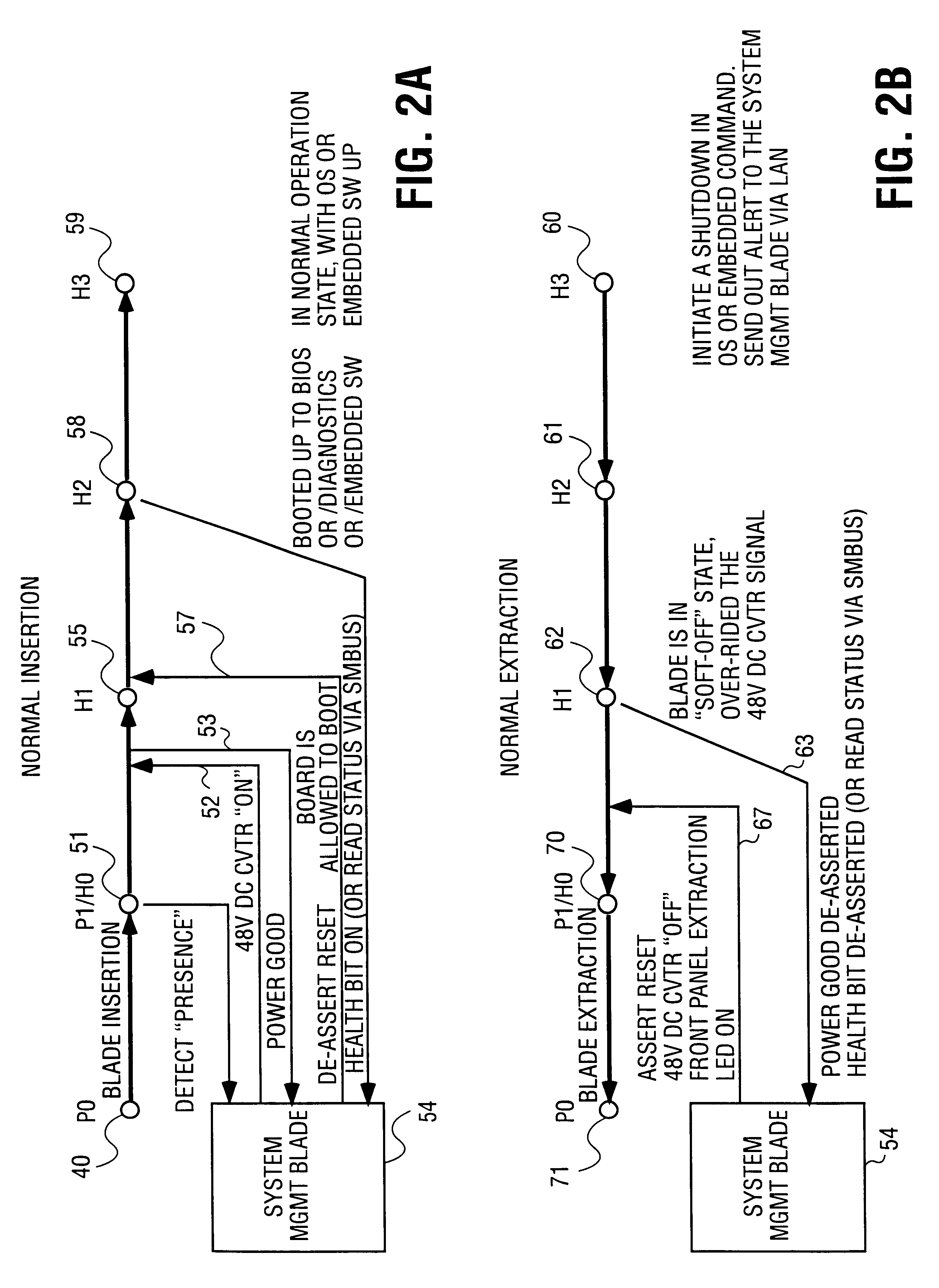
A system is described having a backplane bus and a plurality of blades or boards which may be extracted or inserted while the system is in operation. This is often referred to as "hot swapping."

In the following description, numerous specific details are set forth, such as specific voltages in order to provide a thorough understanding of the present invention. It will be apparent to one skilled in the art that the present invention may be practiced without these specific details. In other instances, well-known circuits and other components have not been set forth in detail in order not to obscure the present invention.

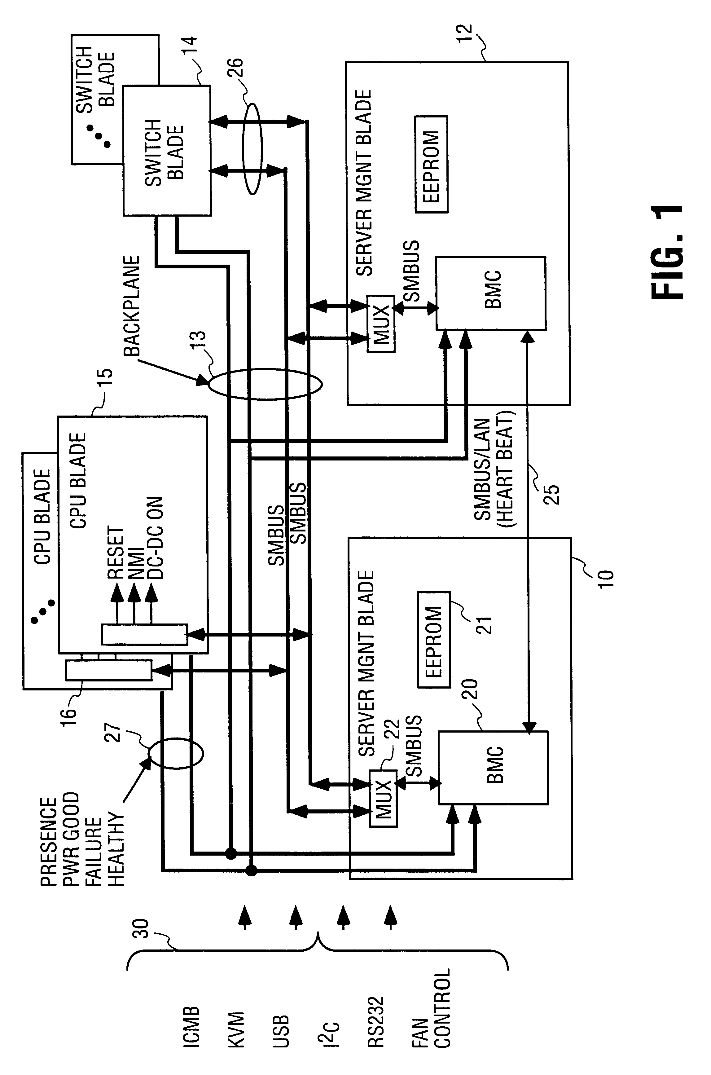
The present invention is described in connection with a server having hot swappable blades. Referring to FIG. 1, the system includes a backplane bus only a portion of which is shown in FIG. 1. Lines 13 and buses 30 are the only portion of the backplane shown, power and ground lines are not shown. The buses shown by the bracket 30 include the Interchassis Management Bus ...


PUM


Abstract

A hot swappable system is described. It included software controlled hot swapping operations which provided a graceful booting or power-down of the system. In the even of force insertion or extraction of the system blades, a set of hardware features (such as using different pin lengths in the connectors and dampening resistor) prevents these types of operations from damaging the system hardware or affecting the operation states of other blades within the system.

Description

1. Field of the InventionThe invention relates to the field of systems with hot swappable components.2. Prior Art and Related ArtIn many applications it is necessary to have a system which remains in operation even when under repair. For instance, a server in a network may have boards or blades in a standby mode or with excess capacity. When a blade is detected as having failed, other blades that were in a stand-by mode take over while the failed blade is replaced. Alternatively, blades with excess capacity are used to pick-up the tasks of the failed blade while it is replaced. Generally, an alarm or other indication is given to an operator indicating that a failure has occurred. The operator is then able to remove the failed blade and reinsert a good blade. One of the major problems in these systems is the management of power as these changes occur.Often in such systems connectors are used having pins of different lengths which cooperatively engage sockets. For instance, a backplan...

Claims


Application Information

Patent Timeline
IPC IPC(8): G06F13/40
CPCG06F13/4081
Inventor WONG, HONG W.
Owner INTEL CORP
Why Eureka
Try Eureka