Method and rinsing equipment for the cleaning of especially filter plates in an electro-filter

a filter plate and filter technology, applied in the direction of electrode cleaning, electrostatic separation, electrode construction, etc., can solve the problems of high operational loss, considerable health risk for personnel, and considerable cost of thorough cleaning, and achieve the effect of high efficiency, low consumption of power and water, and high efficiency

Inactive Publication Date: 2003-03-18
ORECO
View PDF9 Cites 12 Cited by
  • Summary
  • Abstract
  • Description
  • Claims
  • Application Information

AI Technical Summary

Benefits of technology

By setting the displacement and the rotation so that the jet path assumes a mutually uniform distance, a highly efficient cleaning of the plates is achieved.
By letting the displacement correspond to a whole number of spaces between the plates, a compact construction of the equipment will be achieved, which at the same time results in a high efficiency and a minimum consumption of power and water.
Finally, it is advantageous to use the equipment for washing the plate elements corresponding to plate elements in an electro-filter.

Problems solved by technology

If such a cleaning has not been effected, the personnel will be exposed to a considerable health risk due to the dust.
The result is that considerable costs are connected with this thorough cleaning, which in turn involves great operational losses due to the relatively long period of time required for the cooling and the cleaning of the filter.
However, this plant is not particularly efficient, and with the comprehensive chain drive for both nozzles and reflectors it constitutes a very complicated construction.
Moreover, the mechanical parts are disposed inside the filter housing where they are exposed to the aggressive dust, which means that the mechanical parts must be made of expensive materials.
The plant is therefore vulnerable and subject to operational disturbances because of the dust which is deposited on the driving mechanism.
However, this plant is unable to clean the filter housing of dust in a manner whereby the insides of the housing can be inspected without risk.

Method used


Image

  • Method and rinsing equipment for the cleaning of especially filter plates in an electro-filter
  • Method and rinsing equipment for the cleaning of especially filter plates in an electro-filter
  • Method and rinsing equipment for the cleaning of especially filter plates in an electro-filter

Examples


Embodiment Construction

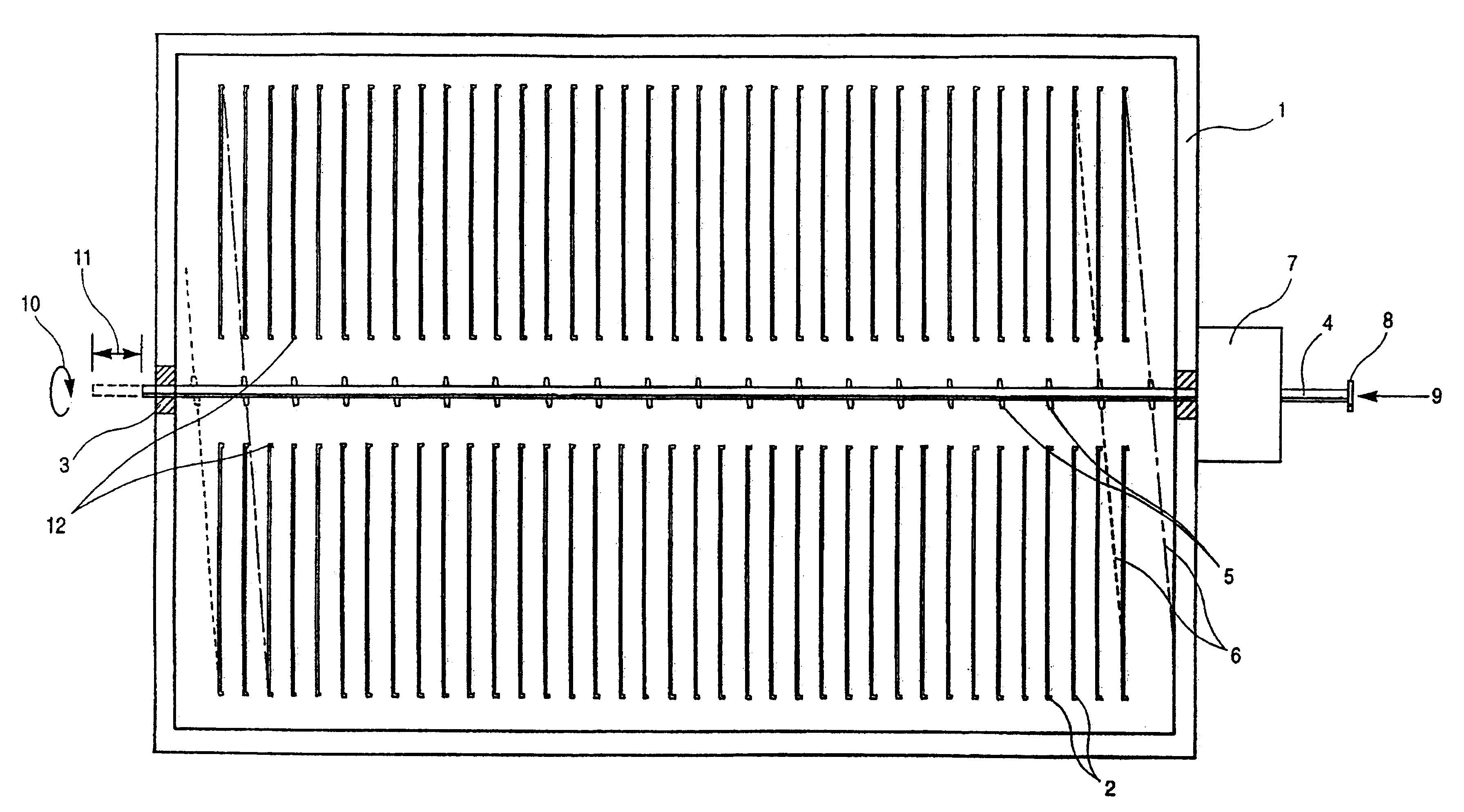
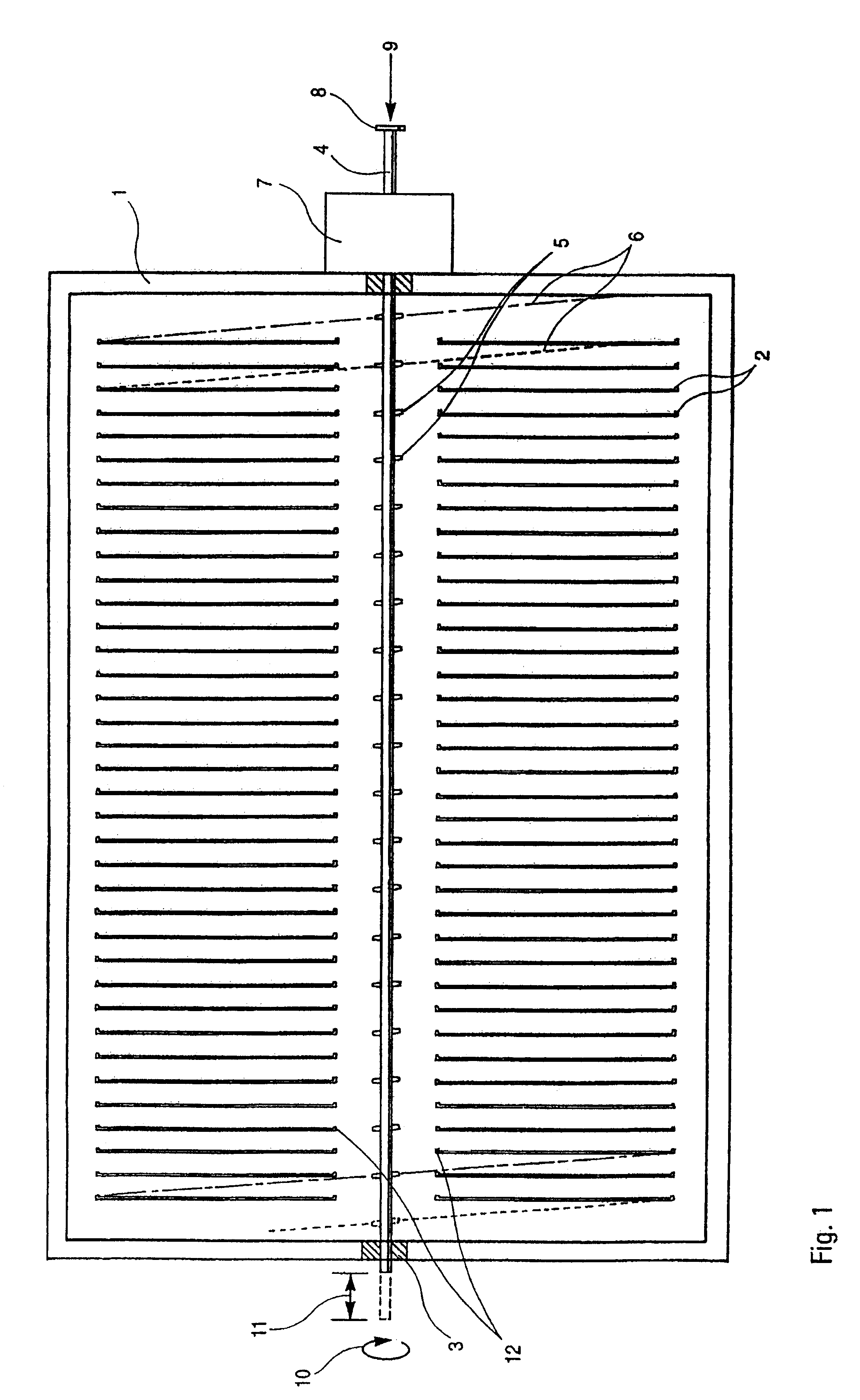
An example embodiment of cleaning equipment according to the invention will now be described with reference to FIG. 1, which shows an electro-filter seen from above, in that the top of the housing is removed. The filter is built into a closed, dust-proof filter housing 1 of a commonly-known kind. In this example, inside the housing there are mounted two rows of filter plates 2 in such a manner that they extend throughout the whole length of the housing, and with their side edges 12 on a line for the formation of an intermediate opening.

The plates 2 are mounted mutually parallel and with the same mutual distance for the formation of uniform spaces between the plates 2.

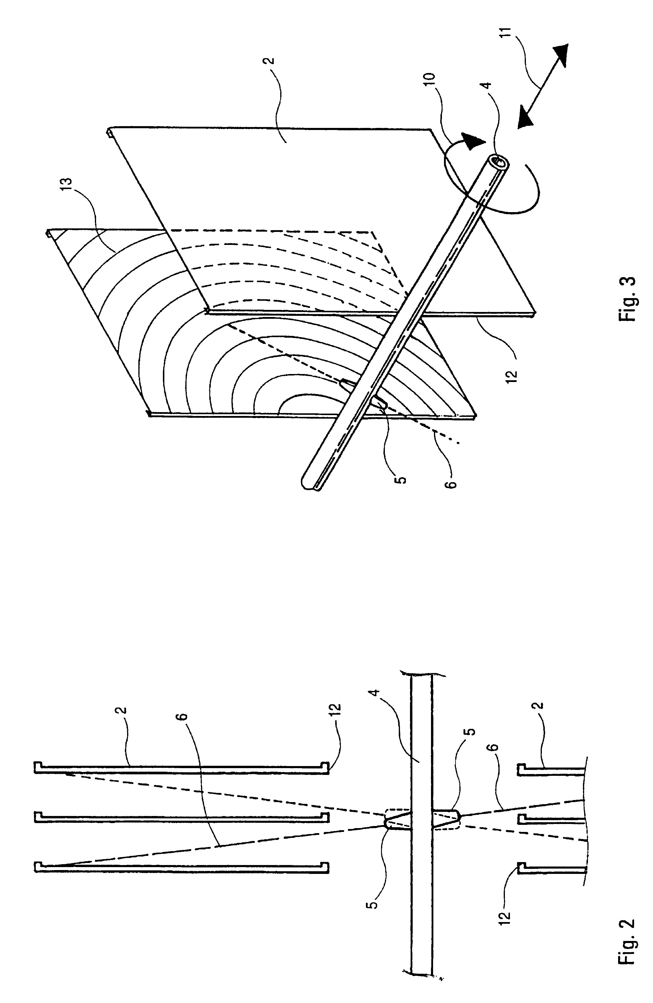
In the intermediate opening between the rows of plates, a pipe 4 is mounted in not-shown bearing brackets, said pipe extending through the housing's one wall which, as indicated in the drawing, can have built-in bearings 3.

The pipe 4 is connected to driving means which are built into a drive unit 7 which is mounted on t...


PUM


Abstract

Filter plates in an electro-filter are cleaned using nozzles which, during spraying, are displaced longitudinally with the side edges of the filter plates while at the same time being rotated. The nozzles are mounted in a plane slightly different from the plane of the filter plates to enable the spray jets to reach the furthermost areas of the plates when the nozzles are at the greatest angle of incidence during washing.

Description

This application is a national stage of a PCT International Patent application no. PCT / DK98 / 00285, filed on Jun. 29, 1998.PRIOR ART TECHNIQUEThe invention concerns a method for the rinsing of especially filter plates for fly ash in an electro-filter built into a filter housing, by means of a cleaning medium which under pressure is sprayed on the plates via movable nozzles, whereby the plates are cleaned.An electro-filter comprises a filter housing in which one or more rows of mutually parallel filter plates are mounted, and which are electrically charged for the trapping of dust particles which are contained in the flue gas which is led through the filter housing.These dust particles, fly ash, are loosened from the plates by mechanical means and are precipitated so that they can subsequently be removed.However, the filter must be periodically inspected, which is why the insides of the filter housing such as the plates must be thoroughly cleaned of dust before personnel can be sent i...

Claims


Application Information

Patent Timeline
Patent Type & Authority Patents(United States)
IPC IPC(8): B03C3/78B03C3/34B03C3/47
CPCB03C3/78B05B3/1021B05B3/1064
Inventor JEPSEN, ERIK LUND
Owner ORECO
Why Eureka
Try Eureka