Disk player, and turntable incorporating self-compensating dynamic balancer, clamper incorporating self-compensating dynamic balancer and spindle motor incorporating self-compensating dynamic balancer adopted for disk player
a technology of dynamic balancer and disk player, which is applied in the direction of mechanical equipment, record information storage, instruments, etc., can solve the problems of increasing the cost of the product, the rotational shaft of the spindle motor becomes serious, and the eccentric center of gravity of the disk, so as to achieve the effect of reducing external vibration and increasing weigh
- Summary
- Abstract
- Description
- Claims
- Application Information
AI Technical Summary
Benefits of technology
Problems solved by technology
Method used
Image
Examples
first embodiment
As shown in FIG. 4, the self-compensating dynamic balancer 400 includes a circular tube 410 whose cross-section is rectangular having a race 450 and a mobile unit 420 movably disposed inside the race 450.
The tube 410 includes a main body 412 through which the race 450 is formed and a cover member 413 for sealing the race 450 in a state in which the mobile unit 420 is sealed therein. The tube 410 rotates coaxially with the rotational shaft 130.
The coupling between the cover member 413 to the main body 412 is made by using an adhesive, a groove and protrusion assembly formed on the cover member 413 and main body 412 at corresponding positions, or a screw. The detailed description thereof will be omitted since such coupling methods are well known.
The mobile unit 420 includes a plurality of rigid bodies 430 and / or a fluid 440 which can move outward from the rotational center by a centrifugal force generated during rotation of the tube 410.
FIG. 5 shows the race 450 in which a plurality o...
second embodiment
As shown in FIG. 7, the self-compensating dynamic balancer includes first and second rectangular cross-sectioned tubes 410a and 410b arranged concentrically and adjacent to each other and first and second mobile units 420a and 420b respectively disposed inside the first and second tubes 410a and 410b to be capable of moving.
The respective first and second tubes 410a and 410b independently serve as a balancer and can finely balance and reduce the orbits of the rotational shaft 130. In this case, since each of the first and second mobile units 420a and 420b is actually the same as that of the mobile unit 420 described with reference to FIGS. 5 and 6, a detailed description thereof will be omitted.
The first and second tubes 410a and 410b and the mobile units 420a and 420b respectively installed therein can be configured as shown in FIG. 8. That is, the width and height of the first race 450a formed in the first tube 410a can be configured different from those of the second race 450b fo...
third embodiment
As shown in FIGS. 17 and 18, the self-compensating dynamic balancer 400 includes a support plate 461 perpendicularly fixed to the rotational shaft 130 and at least one pivoting plate 465 hinge-coupled to the support plate 461 and being parallel to the same. In this case, it is preferable that a pair of the support plates 461 is provided parallel with each other and the pivoting plate(s) 465 is(are) coupled therebetween. The pivoting plate 465 is pivot-coupled between the support plates 461 by a fixing pin 463.
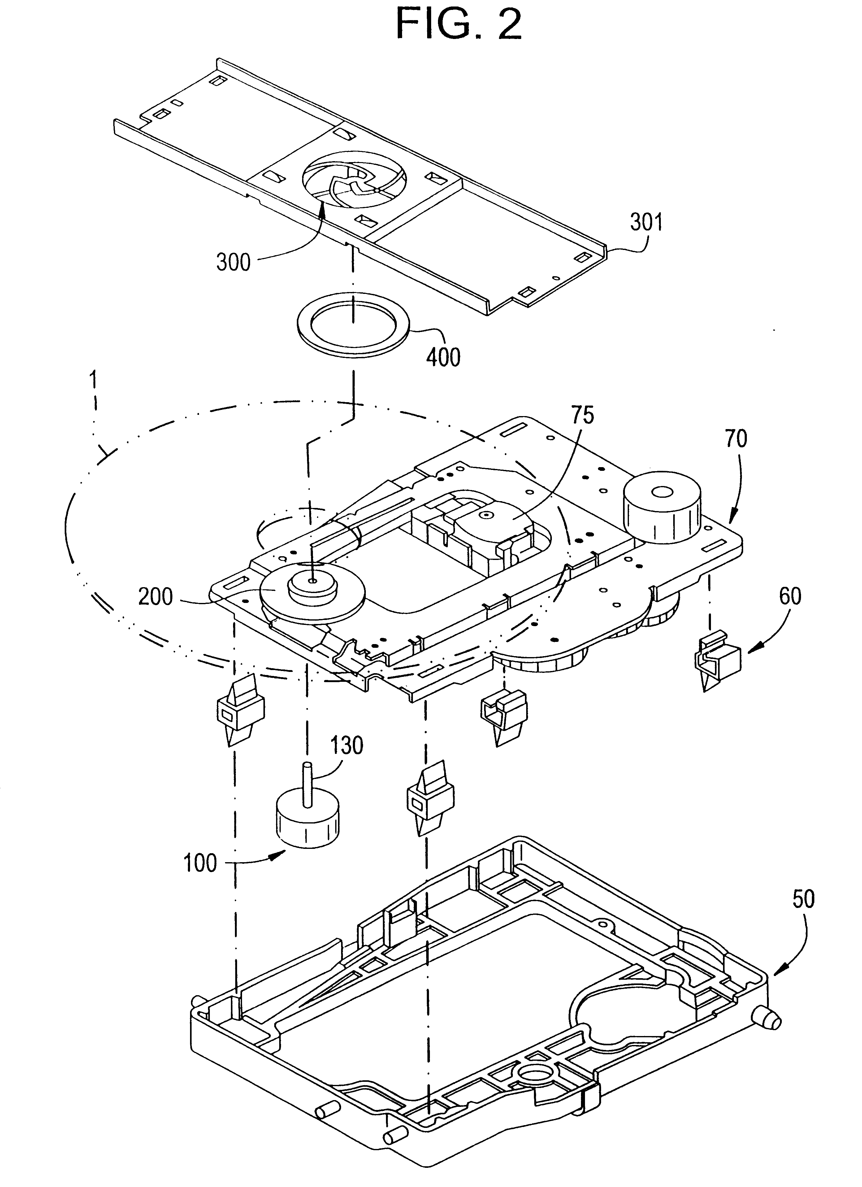
Referring to FIGS. 19 and 20, a turntable 200 incorporating a self-compensating dynamic balancer according to a first embodiment of the present invention will now be described.
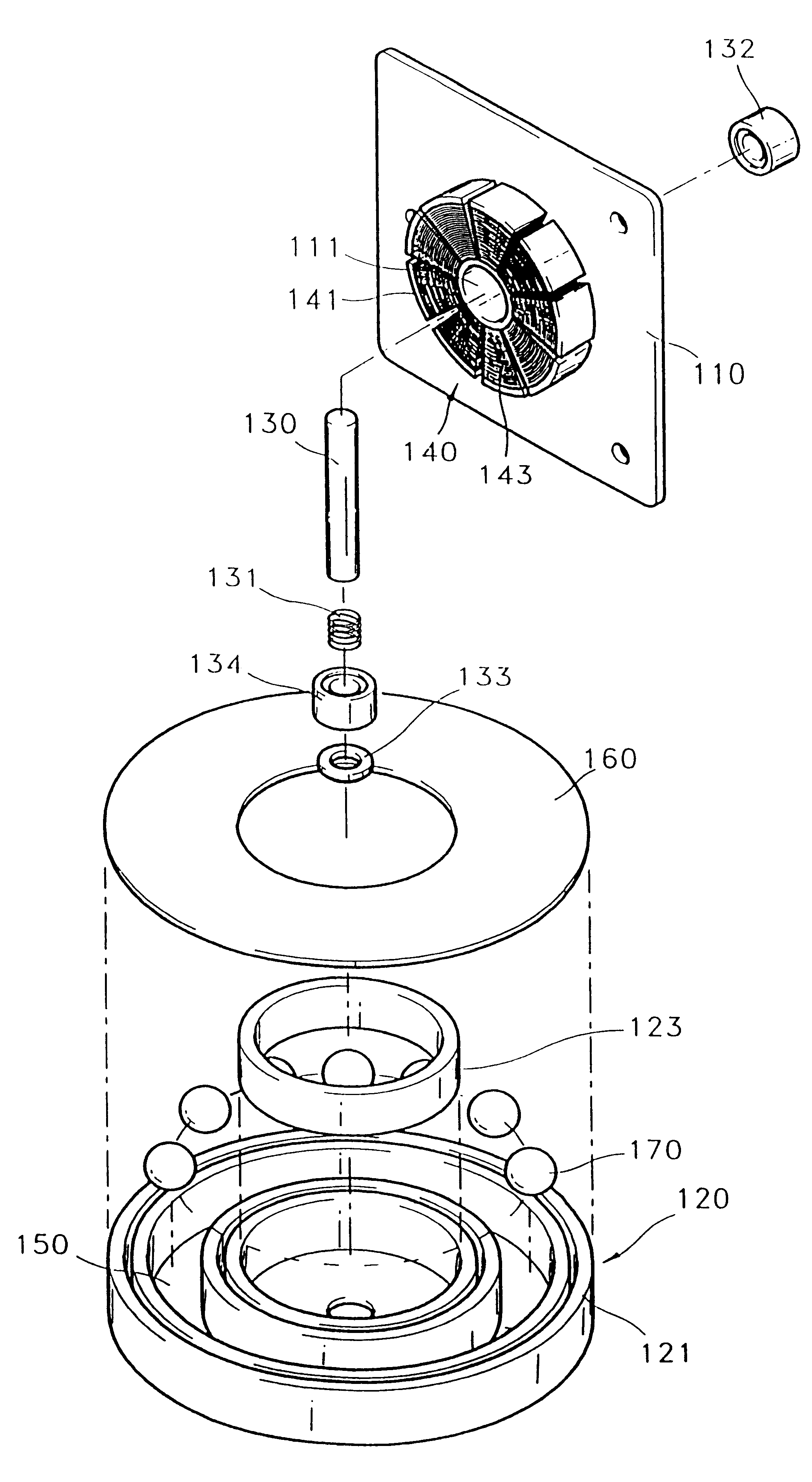
A placing member 210 of the turntable 200 is coupled to the rotational shaft 130 of the spindle motor 100. For that purpose, a coupling hole 240 is formed at the center of the placing member 210 so that the rotational shaft 130 is inserted into and is fixed to the inside of the coupling hole 240. A circul...
PUM
 Abstract
Description
Claims
Application Information
 - R&D
- Intellectual Property
- Life Sciences
- Materials
- Tech Scout
- Unparalleled Data Quality
- Higher Quality Content
- 60% Fewer Hallucinations
Browse by: Latest US Patents, China's latest patents, Technical Efficacy Thesaurus, Application Domain, Technology Topic, Popular Technical Reports.
© 2025 PatSnap. All rights reserved.Legal|Privacy policy|Modern Slavery Act Transparency Statement|Sitemap|About US| Contact US: help@patsnap.com


