Heating system

a technology of heat exchanger and coolant input, which is applied in the direction of machines/engines, heating types, lighting and heating apparatus, etc., can solve the problems of increased fuel consumption and exhaust emissions, increased fuel consumption, and slight heat loss

Inactive Publication Date: 2003-03-25
ROBERT BOSCH GMBH
View PDF14 Cites 9 Cited by
  • Summary
  • Abstract
  • Description
  • Claims
  • Application Information

AI Technical Summary

Benefits of technology

According to the invention, a combustion chamber is connected to the exhaust system of the internal combustion engine in the region of an exhaust manifold of the internal combustion engine, between outlet valves and a exhaust gas catalytic converter, via an exhaust line. As needed, the combustion chamber is put into operation, so that by it, hot exhaust gases of the exhaust system of the engine are heated. This includes primarily the exhaust gas catalytic converter, which very quickly reaches its optimal operating temperature, but also the exhaust conduits as far as the outlet valves, and as a result, the engine itself and especially its cylinder head reaches its operating temperature faster.To achieve a more-intensive heat exchange between the combustion chamber and the engine, it is expedient that coolant conduits of a heat exchanger surround the combustion chamber and are connected to a coolant system of the engine. Thus the combustion chamber can on the one hand already preheat the engine before the engine is started, and on the other, the heater connected to the coolant system of the engine can take care of the passenger compartment. Via electronically triggered valves, the quantity of heat can be distributed to suit existing priorities.In supercharged engines, the combustion chamber can also serve to improve the response performance of the exhaust gas turbocharger, by increasing the quantity and energy of the exhaust gas in the lower rpm range. The resultant higher rpm of the exhaust gas turbine and the radial compressor makes a higher charge pressure possible, which leads to improved acceleration of the engine at more favorable efficiency. The exhaust gas turbine is expediently disposed upstream of the exhaust gas catalytic converter and can be circumvented by a bypass that has a control device. As a result, the exhaust gas turbine can be regulated. Furthermore, because of the bypass, hot exhaust gases while the engine is at a stop reach the catalytic converter directly and already bring it to a suitable operating temperature before the engine is started.By means of the heating system of the invention, it is thus possible to meet all the demands made of a modern internal combustion engine with only a single combustion chamber and at little engineering effort and expense.

Problems solved by technology

In some operating states of an internal combustion engine, such as cold starting, short trips, or long downhill trips by motor vehicles, the heat input into the coolant from the engine itself is no longer sufficient, especially if the efficiency of the engine is very high, as in the case of direct gasoline injection, high pressure diesel injection with a common rail, or a highly charged engine with a turbocharger, since then only slight heat losses occur.
Accordingly, the engine and its catalytic converter do not reach their optimal temperatures within the brief available time, or do so only quite late, which leads to increased fuel consumption and increased exhaust emissions.
Since at low outdoor temperatures considerable amounts of heat are required to de-ice the vehicle windows or to heat the passenger compartment, both driving safety and comfort are restricted.
Chemical auxiliary heaters, such as burners, do offer great comfort because of the capability of heating even while the engine is at a stop, but are relatively expensive.
Conventional electrical auxiliary heaters operating on the principle of resistance heating are highly limited in power, because the generator cannot make enough current available.

Method used


Image

  • Heating system
  • Heating system

Examples


Embodiment Construction

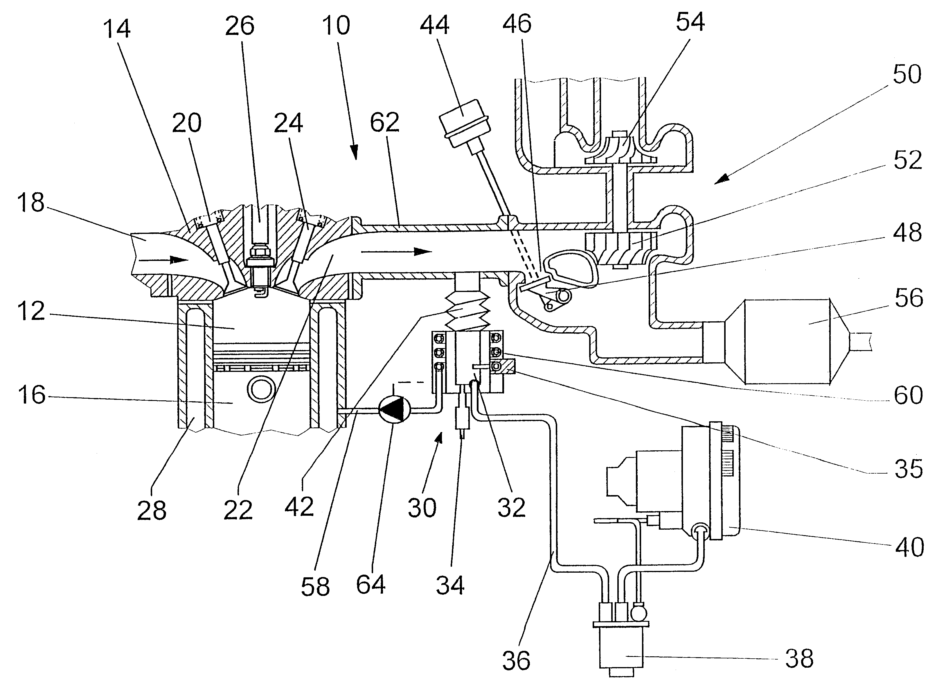
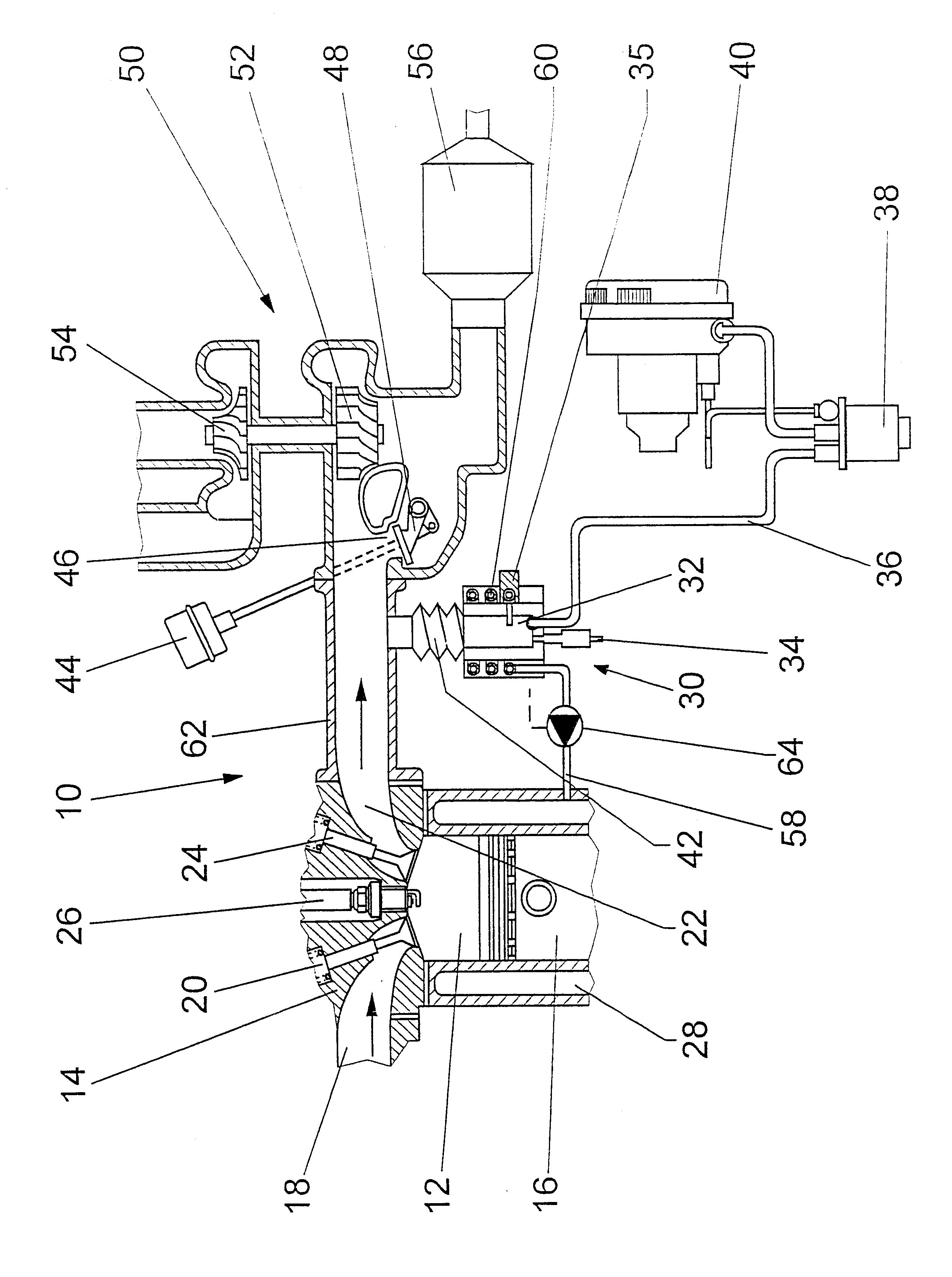
The internal combustion engine 10 has cylinders 12, which between pistons 16 and a cylinder head 14 form work chambers, to which air is delivered via inlet conduits 18. Via outlet conduits 22, the piston 16 expels the exhaust gas into an exhaust manifold 62. The inlet conduits 18 and the outlet conduits 22 are controlled by inlet valves 20 and outlet valves 24, respectively. An ignition aid 26, in the form of a spark plug in the case of the Otto process, initiates the combustion of the fuel-air mixture in the cylinder 12, while an ignition aid 26, in the form of a glow plug in the diesel process, serves to preheat the combustion air.

A combustion chamber 32 of a heater 30 is connected to the exhaust manifold 62 of the engine 10 via an exhaust line 42. The exhaust line 42 is expediently embodied as a metal bellows, so that it can compensate for different thermal expansions as a consequence of different temperatures between the combustion chamber 32 and the exhaust manifold 62. Fuel is...


PUM


Abstract

The invention is based on a heating system for a motor vehicle, which is driven by an internal combustion engine (10), in which a heater (30) includes a combustion chamber (32) with a fuel injection device (34) and an ignition device (35) and also includes an air blower (40), and is triggered as a function of operating parameters and / or ambient parameters of the motor vehicle and / or of the internal combustion engine (10) or by actuating signals.It is proposed that the combustion chamber (32) is connected to the exhaust system (62) of the internal combustion engine (10) in the region of an exhaust manifold (62) of the internal combustion engine (10), between outlet valves (24) and a exhaust gas catalytic converter (56), via an exhaust line (42).

Description

PRIOR ARTThe invention is based on a heating system as generically defined by the preamble to claim 1.In some operating states of an internal combustion engine, such as cold starting, short trips, or long downhill trips by motor vehicles, the heat input into the coolant from the engine itself is no longer sufficient, especially if the efficiency of the engine is very high, as in the case of direct gasoline injection, high pressure diesel injection with a common rail, or a highly charged engine with a turbocharger, since then only slight heat losses occur. Accordingly, the engine and its catalytic converter do not reach their optimal temperatures within the brief available time, or do so only quite late, which leads to increased fuel consumption and increased exhaust emissions.Since at low outdoor temperatures considerable amounts of heat are required to de-ice the vehicle windows or to heat the passenger compartment, both driving safety and comfort are restricted. Furthermore, futur...

Claims


Application Information

Patent Timeline
Patent Type & Authority Patents(United States)
IPC IPC(8): F01N3/20F02B37/18F02B37/20F02B37/12F01P5/00F01P7/14F01P5/12F01N13/08
CPCF01N3/2033F02B37/20F02B37/18F01N2240/02F01N2470/12F01P2005/125F01P2007/146F01P2060/18Y02T10/26F23N2033/06F23N2035/30F23N2041/14Y02T10/144F23N2233/06F23N2235/30F23N2241/14Y02T10/12Y02A50/20F01N3/38
Inventor BAEUERLE, MICHAELRIES-MUELLER, KLAUS
Owner ROBERT BOSCH GMBH
Why Eureka
Try Eureka