Detachable fast-coupling having an automatic assembly indicator

Inactive Publication Date: 2003-03-25
A RAYMOND & CO
View PDF7 Cites 44 Cited by
  • Summary
  • Abstract
  • Description
  • Claims
  • Application Information

AI Technical Summary

Benefits of technology

It is the task of the invention to construct the assembly indicator in such a way that the indicator part, after being introduced into the receiving space, is held securely and without movement and that

Problems solved by technology

The disadvantages of this assembly indicator include the fact that the indicating part with its retaining members and stop ring is inserted with play

Method used


Image

  • Detachable fast-coupling having an automatic assembly indicator
  • Detachable fast-coupling having an automatic assembly indicator
  • Detachable fast-coupling having an automatic assembly indicator

Examples


Embodiment Construction

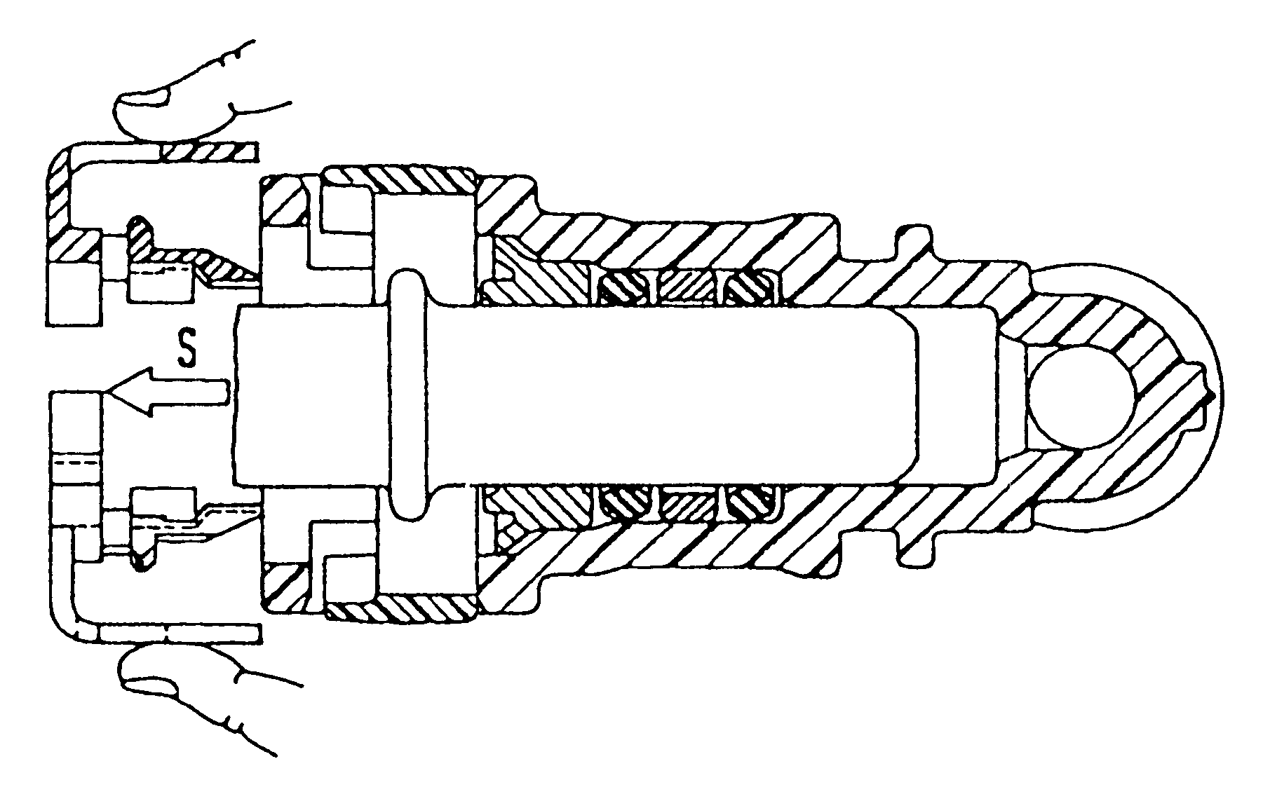
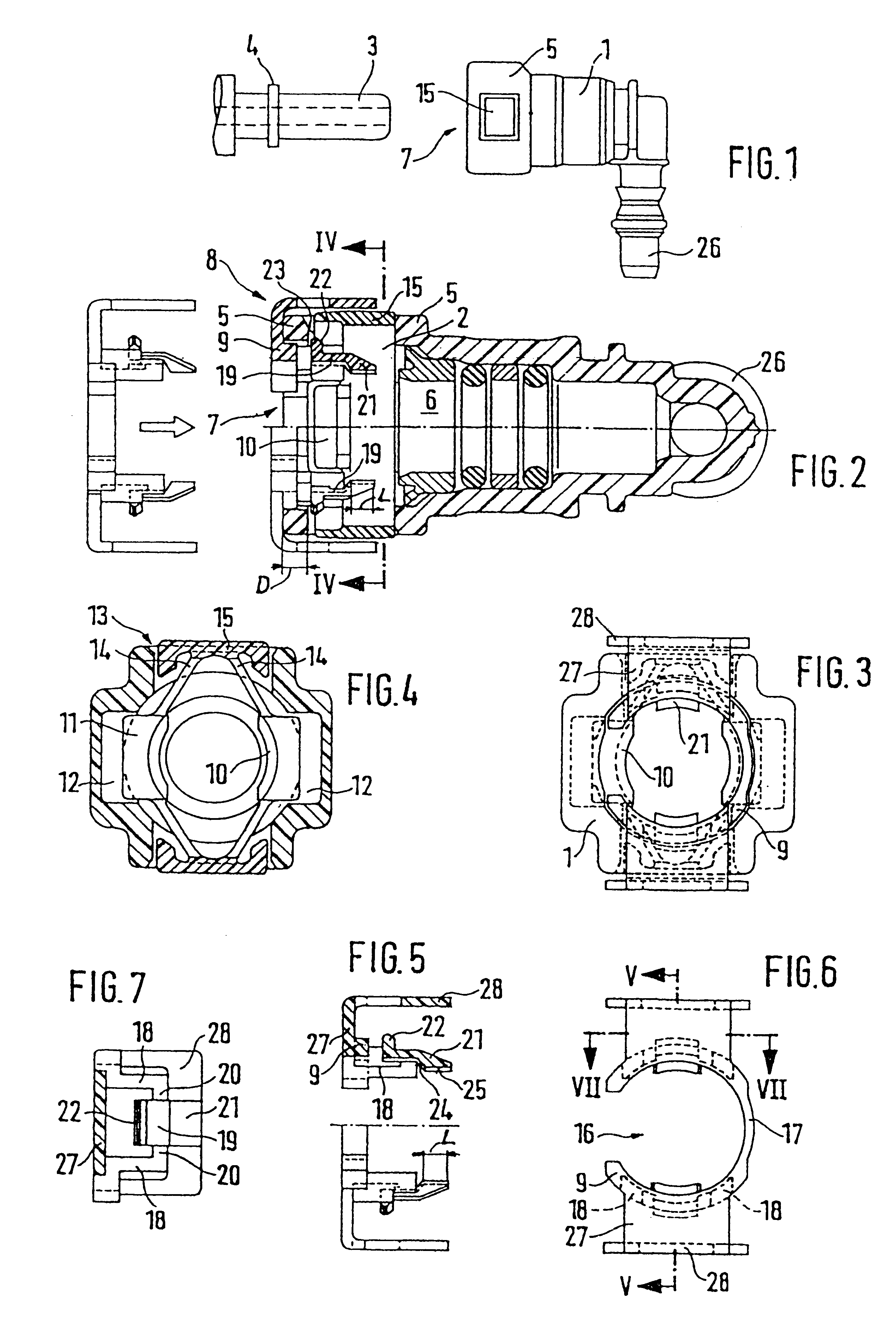
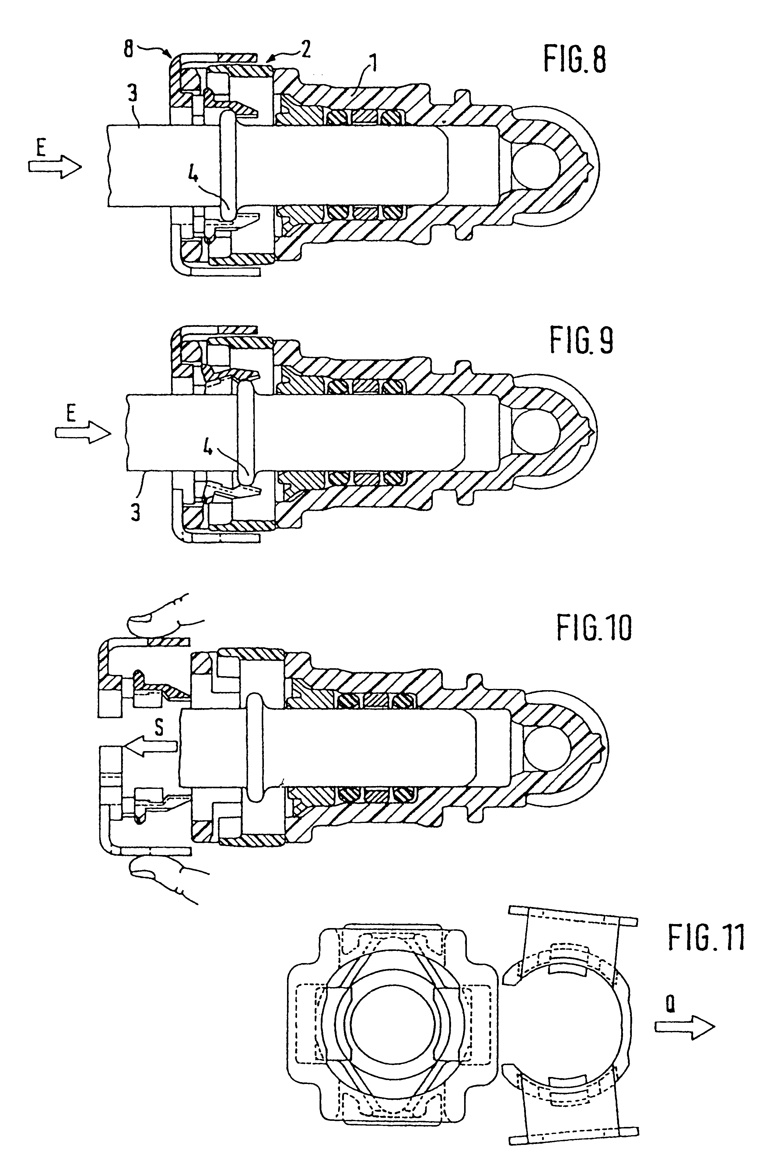
The fast-coupling shown in the figures, as can be seen in FIG. 1, includes a receiving housing (1) made of a synthetic material with a tubular connecting piece (26) for the purpose of connecting a fluid line, not shown, and of a cylindrical receiving space (6) for the introduction of a tubular insertion part (3) with a peripheral retaining rib (4).

The insertion part (3) may be the end of a sturdy metal pipe used, for example, for fuel lines. However, it may also--exactly like the receiving housing--be formed from a rigid synthetic material or another injection molded material, which can be connected to a fluid line in the same manner as the connecting piece (26) of the receiving housing. Alternatively, it may be molded or otherwise fastened to a fuel container or fuel distributor.

In the front area of the receiving space (6), there is a retaining element (2) made of a hard elastic synthetic material which can be introduced into the receiving space (6) through an opening in the cylind...


PUM


Abstract

A detachable coupling includes a housing having wall, an end that has an inner wall, and a receiving space that has an opening in the end. The opening and the receiving space receives a tubular insertion part that has a retaining rib. An indicating part is removably mounted to the end of the receiving housing and includes a support ring and a lever. The lever has a free end and a inner end and is pivotally mounted to the support ring and extends into the receiving space. A support projection is positioned on the inner end of the lever and contacts the inner wall. Insertion of the tubular insertion part causes the retaining rib to contact the free end of the lever and results in the pivoting of the lever. Pivoting of the lever disengages the support projection from the inner wall and dismounts the indicating part from the housing.

Description

1. Field of the InventionThe present invention relates to a detachable fast-coupling with an automatic assembly indicator for connecting fluid lines.2. Reference to Related ArtFast-couplings are used, for example, in the motor vehicle industry in order to connect fluid lines to each other or to insertion parts molded or otherwise attached to fuel containers or fuel distributors. Typically, there is not only a simple and easy assembly as well as an absolutely sealed connection after the insertion part is secured in the coupling housing, but the coupling must also, when necessary, be easily detachable.The present invention is based on a fast-coupling with an assembly indicator known from EP 0 547 489 A1. The indicator part shown there consists of a ring which can be positioned in front of the insertion opening the receiving housing and which supports itself on the latter's facing wall, as well as of at least two retaining members facing each other and projecting into the receiving spa...

Claims


Application Information

Patent Timeline
IPC IPC(8): F16L37/00F16L37/098F16L37/08F16L37/084
CPCF16L37/0985F02M69/462F02M61/168F16L2201/10F02M2200/8023F16L37/084
Inventor RAYMOND, ALBERTMORETTI, ERMINIOMARTIN-COCHER, DANIELLESSER, HANS-JURGEN
Owner A RAYMOND & CO
Why Eureka
Try Eureka