Ferrule boot for optical connectors

a technology of optical connectors and boot covers, applied in the field of enhanced multi-fiber boot covers, can solve the problems of significantly increasing manufacturing times and costs, affecting etc., and achieves the effects of improving the retention of optical fiber ribbons, and improving the efficiency of installation

Inactive Publication Date: 2003-03-25
CORNING OPTICAL COMM LLC
View PDF9 Cites 57 Cited by
  • Summary
  • Abstract
  • Description
  • Claims
  • Application Information

AI Technical Summary

Benefits of technology

Another object of this invention is to provide an enhanced boot for a terminal connector that improves automated assembly.
Another object of this invention is to provide an enhanced boot for a terminal connector that improves optical fiber ribbon retention.
These and other objects, features, aspects, and advantages of this invention are realized by a ferrule boot for protecting an optical fiber ribbon connected to a terminal connector. The ferrule boot comprises a body member defining a channel extending therethrough, and a first tapered lead-in located at a distal end of the channel. The first tapered lead-in is sized and dimensioned such that the optical fiber ribbon with the optical fibers stripped and exposed is insertable through the boot from the distal end of the channel to a proximal end of the channel and then is affixed to the ferrule boot by adhesive. The first tapered lead-in is connected to a second tapered lead-in, and the second tapered lead-in prevents the adhesive from wicking to the outside of the ferrule boot.
The channel further comprising a substantially straight section sized and dimensioned to fit intimately over the outside of the optical fiber ribbon. This substantially straight section centers and guides the exposed optical fibers to the center of the proximal end of the channel. The ferrule boot also has a lip positioned proximate to the proximal end of the channel and oriented at an angle with the channel such that the lip functions as a seal and also facilitates easier insertion. In another embodiment, the lip also provides a lower resistance to movement of the optical fiber ribbon from the distal end of the channel to the proximal end of the channel and provides a higher resistance to movement of the optical fiber ribbon in the opposite direction.

Problems solved by technology

Due to the intimate fit of the boot over the ribbon, the protective layers on the ribbon's matrix cannot be stripped to expose the fragile optical fibers prior to installing the ribbon to the ferrule boot to prevent the optical fibers from breaking.
This tight tolerance and the inability to pre-strip the ribbon prior to assembling the connector hinder automated installation efforts.
Since large numbers of terminal connectors are manufactured every day, the inefficiencies created by current assembly processes that are less than fully automated quickly result in significantly increased manufacturing times and costs.

Method used


Image

  • Ferrule boot for optical connectors
  • Ferrule boot for optical connectors
  • Ferrule boot for optical connectors

Examples


Embodiment Construction

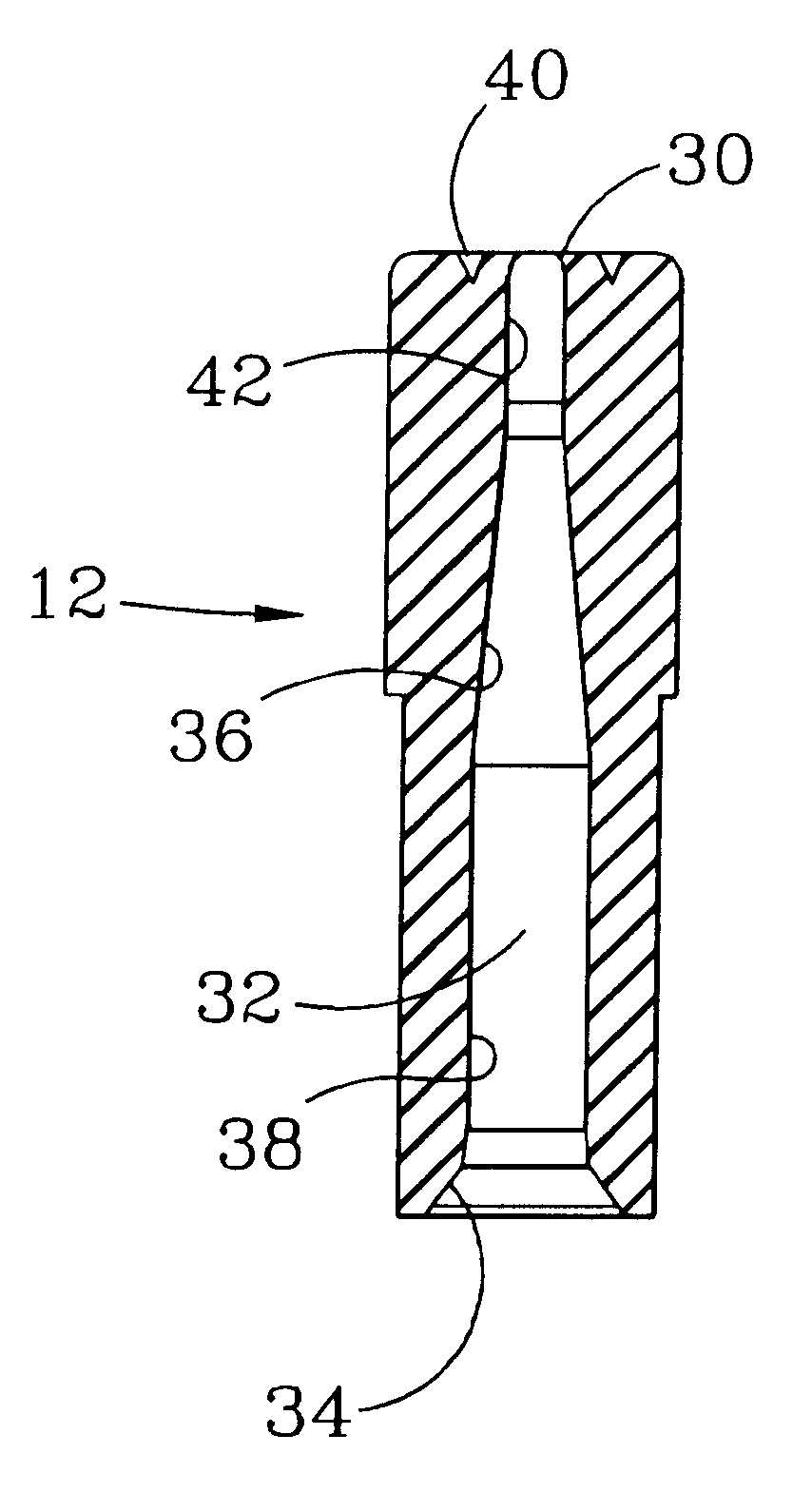
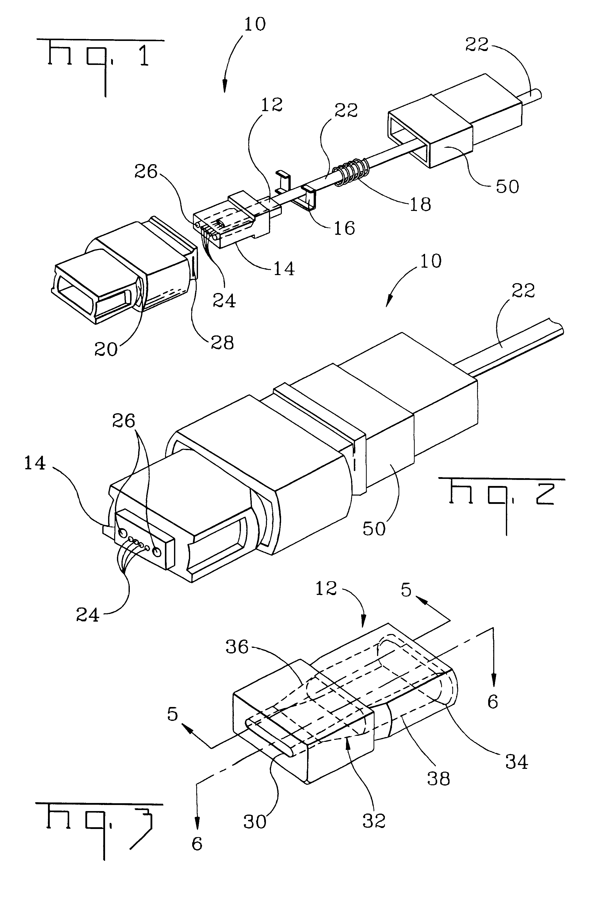
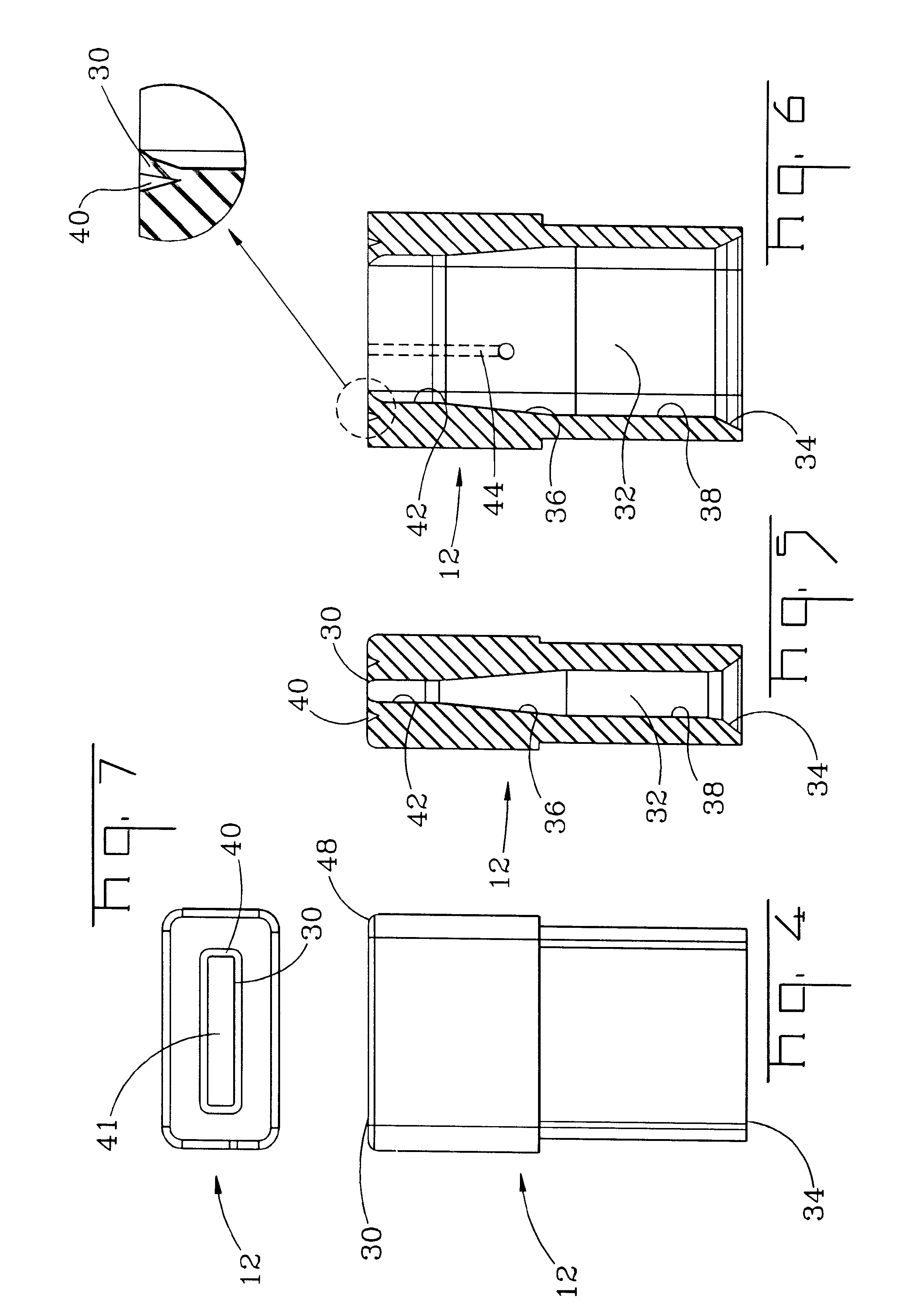
As shown generally in FIGS. 1 and 2, reference number 10 broadly designates the terminal connector in accordance with this invention. Terminal connector 10 comprises at least ferrule boot 12, ferrule 14, stopper 16, spring 18, connector housing 20, and connector boot 50. Connector 10 may have greater or fewer components. As illustrated below, ferrule boot 12 is inserted into the ferrule 14. After the protective matrix is stripped away, the exposed optical fibers 24 of ribbon 22 are inserted into pre-existing optical fiber holes in ferrule 14. An adhesive epoxy is injected into ferrule 14 to secure ribbon 22 and optical fibers 24 and, in turn, to secure ferrule boot 12 with ferrule 14. Ferrule 14 also has two guide pin insertion holes 26 adapted to receive matching guide pins (not shown). Stopper 16 provides a backstop for the guide pins preventing them from entering the boot 50. Stopper 16 also provides an abutting surface for spring 18 to abut. After ferrule boot 12 with ribbon 22 ...


PUM


Abstract

A ferrule boot for attachment to an optical fiber ribbon has a channel extending therethrough. The channel has at its distal end a first tapered lead-in section sized and dimensioned such that the optical fiber ribbon with the internal optical fibers stripped and exposed is insertable through the ferrule boot. The first tapered lead-in section is connected to a second tapered section, and the second tapered section prevents adhesives used to affix the optical fiber ribbon to a ferrule from wicking to the outside of the ferrule boot. The channel has a substantially straight section fitting intimately over the outside of the optical fiber ribbon to center and guide the exposed optical fibers to the center of the proximal end of the channel. In an embodiment, the ferrule boot also has a lip member disposed proximate to the proximal end of the channel to help seal the adhesive and ease insertion. Additionally, the lip may also prevent withdrawal of the optical fiber ribbon. In another embodiment, the ferrule boot also has a vent hole to allow air or other gases trapped in the ferrule boot cavity to vent to the ambient atmosphere.

Description

FIELD OF THIS INVENTIONThis invention relates to a novel structure for a strain relief device for attachment to a terminal connector for an optical fiber or an optical fiber ribbon. More particularly, this invention is directed to an enhanced multifiber boot that is capable of being installed by automated assembly and that has improved ribbon retention.BACKGROUND OF THIS INVENTIONOptical fiber ribbons may include one or more optical fibers capable of transmitting audio, video, text, or other information. Optical fiber ribbons are laid over long distances and must make twists and turns, and, therefore, require connectors to connect discrete segments of optical fiber ribbons together or to connect an optical fiber ribbon to a terminal or signal port of an apparatus or other equipment. As used herein, the term "connector" includes numerous fiber optic connectors which may have a variety of ferrule configurations, including, for example, an MT, MT-S, MTP, MT-RJ and DC connectors. These ...

Claims


Application Information

Patent Timeline
Patent Type & Authority Patents(United States)
IPC IPC(8): G02B6/38
CPCG02B6/3885
Inventor LUTHER, JAMES P.THEUERKORN, THOMASTHROCKMORTON, RODNEY A.
Owner CORNING OPTICAL COMM LLC
Why Eureka
Try Eureka