Scheme for graphical user interface using polygonal-shaped slider

a graphical user interface and polygonal shape technology, applied in the field of graphical user interface using polygonal shape slider, can solve the problems of difficult video data manipulation, inability to manipulate video data that involve a complicated trajectory, and inability to intuitively match the manipulation of the slider with playback video data

Inactive Publication Date: 2003-04-01
NIPPON TELEGRAPH & TELEPHONE CORP
View PDF6 Cites 261 Cited by
  • Summary
  • Abstract
  • Description
  • Claims
  • Application Information

AI Technical Summary

Problems solved by technology

Therefore, the manipulation of the slider does not always agree with playbacked video data intuitively.
The conventional slider is unable to continuously follow the complicated trajectory of moving objects, waveforms, or routes in maps while inputting cont...

Method used


Image

  • Scheme for graphical user interface using polygonal-shaped slider
  • Scheme for graphical user interface using polygonal-shaped slider
  • Scheme for graphical user interface using polygonal-shaped slider

Examples


first embodiment

Referring now to FIG. 2 to FIG. 10, the first embodiment of the GUI scheme using a polygonal-line-shaped slider according to the present invention will be described in detail. The first embodiment enables a user to interactively manipulate and playback spatio-temporal data such as video data using the above polygonal-line-shaped slider that flexibly relates the time and space axes to a two-dimensional display screen.

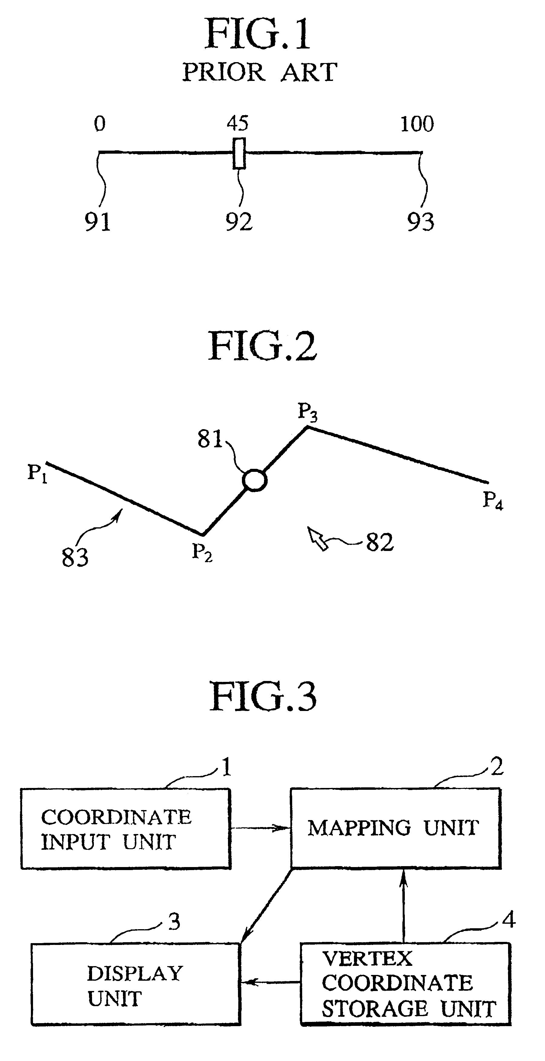
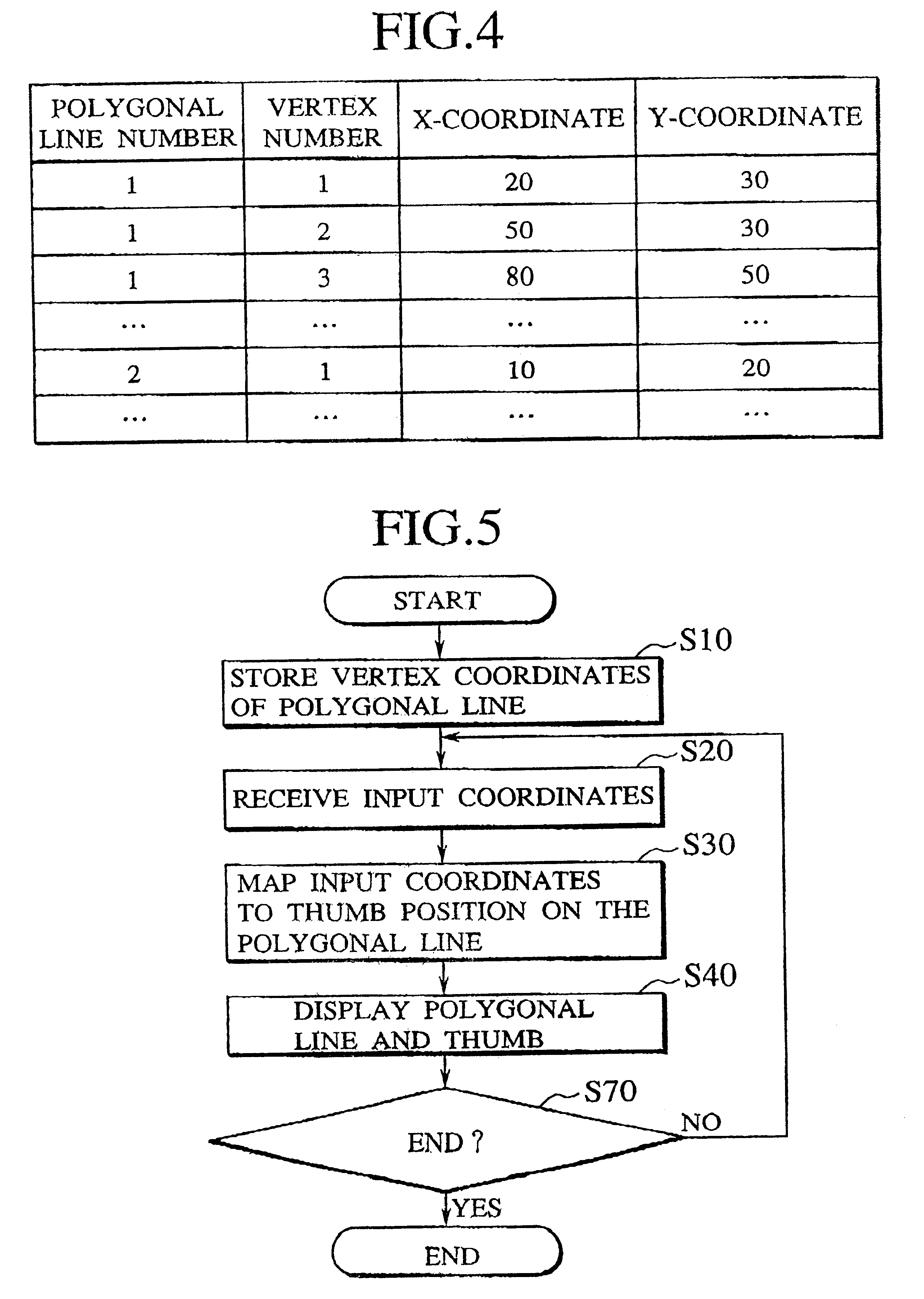
FIG. 3 shows a basic configuration of the polygonal-line-shaped slider apparatus of the first embodiment. The apparatus comprises a coordinate input unit 1, a mapping unit 2, a display unit 3, and a vertex storage unit 4.

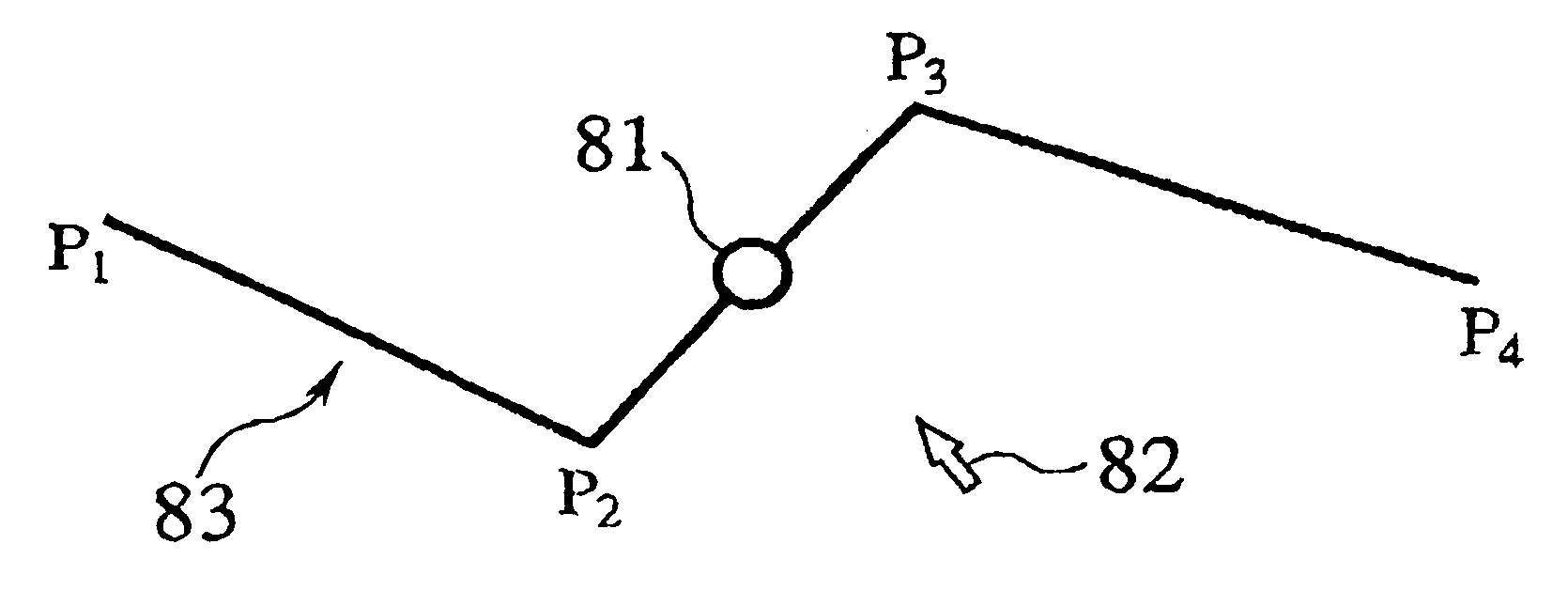
The coordinate input unit 1 is implemented as a pointing device such as a mouse or a touch panel and used to enter input coordinates into the mapping unit 2 so as to store the input coordinates. The mapping unit 2 maps the input coordinates provided by the coordinate input unit 1 to a position of the thumb 81 of the polygonal-line-shaped slider of FIG. 2...

second embodiment

The second embodiment solves the discontinuity problem by using the mapping unit 2 of FIG. 12.

Next, the processing of the mapping unit 2 of the second embodiment will be explained in detail. FIG. 12 shows a detail configuration of the mapping unit 12 according to the second embodiment.

The mapping unit 2 of the second embodiment comprises a bisector generation unit 201, a judging unit 202, a first distance calculation unit 203, a selection unit 204, a second distance calculation unit 205, and an interior division unit 206. According to the input coordinates from the coordinate input unit 1 (FIG. 3) and the vertex coordinates from the vertex storage unit 4 (FIG. 3), the mapping unit 2 determines the position of the thumb on the polygonal line.

FIG. 13 shows a flow chart for a procedure of the processing carried out by the mapping unit 2. The bisector generation unit 201 generates a bisector line for a vertex angle at each vertex of the polygonal line. However, for each endpoint of the ...

third embodiment

Referring now to FIG. 19 to FIG. 23, the third embodiment of the GUI scheme using a polygonal-line-shaped slider according to the present invention will be described in detail. The third embodiment more naturally maps the movement of input coordinates to the position of the thumb on the polygonal line than the second embodiment when the input coordinates are close to the polygonal line. The third embodiment is a modification of the second embodiment in which the mapping unit 2 of FIG. 12 is replaced by the mapping unit 2 of FIG. 19.

When the input coordinates are close to the polygonal line that forms the slider, the second embodiment causes unnatural movement of the thumb along the polygonal line. This will now be explained with reference to FIG. 23. Assume that an input point I is set on a segment BC of the polygonal line ABC. A bisector line l is generated at a vertex B, and a perpendicular line m is drawn through a vertex C of the segment BC. In this case, the mapping unit 2 of t...


PUM


Abstract

A scheme for graphical user interface using a polygonal-line-shaped slider that enables a user to intuitively manipulate-and playback spatio-temporal media data such as video data and animation data without deteriorating the temporal continuity of the data in interactive manipulation and playback of the spatio-temporal media data is disclosed. In this scheme, the slider is composed of a polygonal line composed of at least one segment and a coordinate indicator that is moved along the polygonal line. Data corresponding to coordinates specified by the coordinate indicator is entered. The apparatus according to present invention stores the coordinates of vertexes of the polygonal line, stores input coordinates, maps the input coordinates onto a point on the polygonal line, and positions the coordinate indicator at the point.

Description

1. Field of the InventionThe present invention relates to a scheme for GUI (graphical user interface) using a polygonal-line-shaped slider that serves as an interface for enabling a user to intuitively manipulate and playback spatio-temporal media data such as video data and animation data continuously in time in correspondence to user input with respect to interactive manipulation and playback of the spatio-temporal media data.2. Description of the Background ArtOne of conventional interfaces for interactively manipulating data is a slider. FIG. 1 shows one conventional slider. The slider comprises a segment having a start point 91 and an end point 93, and a thumb 92, where the thumb 92 moves along the segment. A user uses a pointing device such as a mouse or a touch panel to manipulate the thumb 92. A value between the start point 91 and the end point 93 is set in accordance with the movement of the thumb 92. The value corresponding to the position of the thumb 92 is entered into ...

Claims


Application Information

Patent Timeline
IPC IPC(8): G06F3/033A63B69/00G06F3/048
CPCA63B24/0003G06F3/04855G06F3/04847A63B2220/806A63B2220/807
Inventor SATOU, TAKASHIKOJIMA, HARUHIKOTONOMURA, YOSHINOBUAKUTSU, AKIHITO
Owner NIPPON TELEGRAPH & TELEPHONE CORP
Why Eureka
Try Eureka