Log cutting system

a technology of log cutting and cutting blades, which is applied in the direction of metal sawing devices, flat surface machines, manufacturing tools, etc., can solve the problem that none of the prior art devices disclose the unique features

Inactive Publication Date: 2003-04-08
PSI SALES
View PDF21 Cites 25 Cited by
  • Summary
  • Abstract
  • Description
  • Claims
  • Application Information

AI Technical Summary

Problems solved by technology

However, none of the prior art devices disclos

Method used


Image

  • Log cutting system
  • Log cutting system
  • Log cutting system

Examples


Embodiment Construction

)

Turning now descriptively to the drawings, in which similar reference characters denote similar elements throughout the several views, FIGS. 1 through 11 illustrate the present invention being a multi-blade log cutting system.

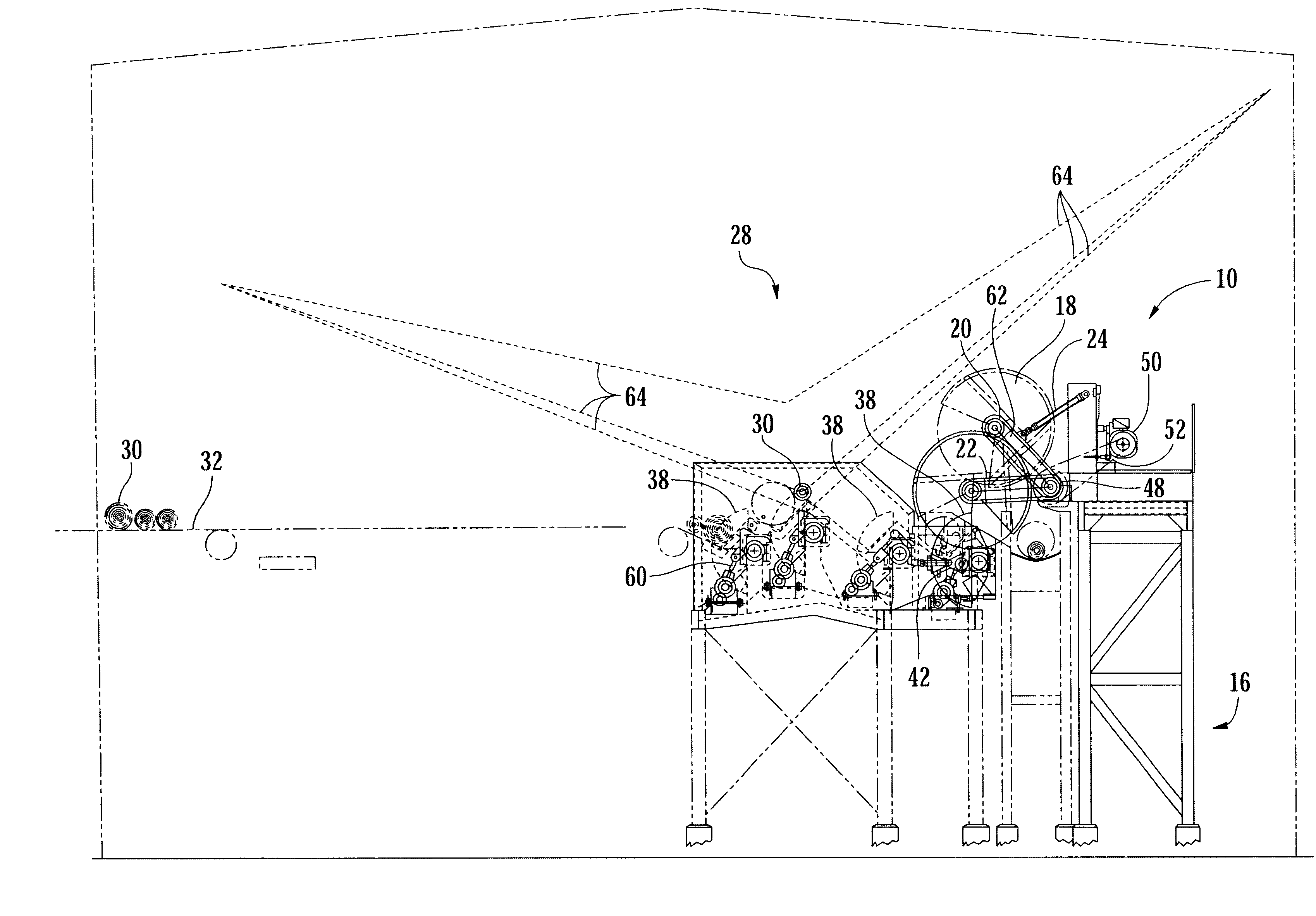
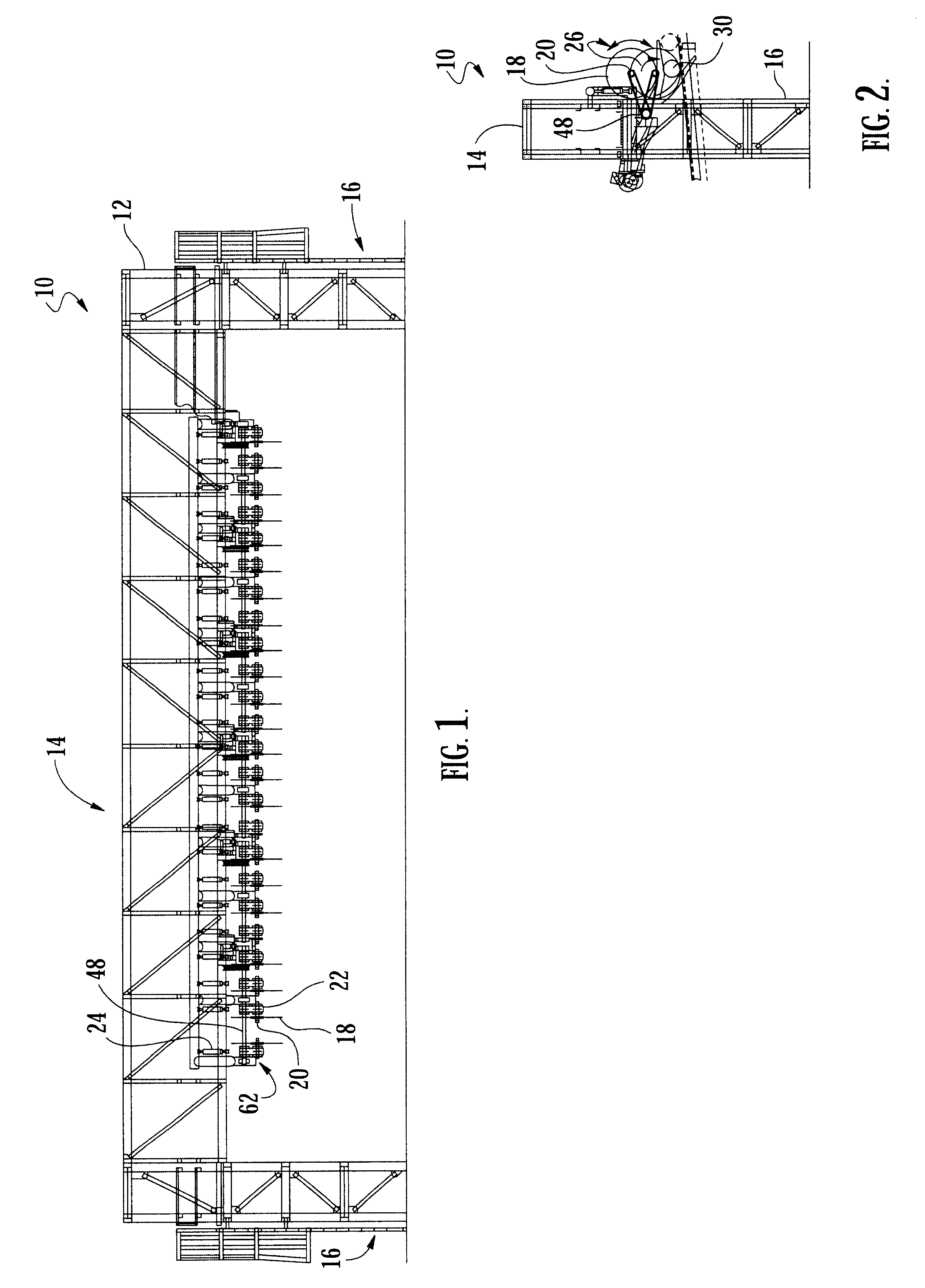
Turning to FIGS. 1 and 8, therein is shown a front elevation view of the present invention 10. Therein is shown the support frame 12 generally having a horizontal central cross member 14 along with a pair of leg-like supports on each end 16. The central member is approximately 65 feet long which is large enough to accommodate tree-length logs and the end members 16 are about 22 feet high. Also shown therein are the multiple cutting blades 18 being rotatably mounted 20 having rotatable drive means 22. Also shown therein are hydraulic lifting means 24, which could use air or fluid for operation, which are used to raise and lower the blade 18 into the proper cutting position. Drive shaft 48 and multiple saw arm 62 are also shown.

Turning to FIG. 2, therein is show...


PUM

PropertyMeasurementUnit
Tensionaaaaaaaaaa

Abstract

The present invention discloses a log sawing system comprising multiple cutting blades. The multiple cutting blades are positioned to cut laterally or perpendicular to the centerline of the log which is to be cut. The logs are transported into cutting position using some type of log positioner. The multiple cutting blades are rotatably mounted on an arm which is pivotally mounted on a shaft in groups, being driven by an electrical or like motor, all of which are mounted onto a platform positioned adjacent to the log to be cut. Hydraulic lifters are used to partially rotate the saw blades into the cutting position adjacent the log. Means utilizing a computer and lasers are provided to develop a log cutting solution to best utilize the logs.

Description

1. Field of the InventionThe present invention relates generally to log cutting systems and, more particularly, is concerned with a multi-blade log cutting system.2. Description of the Prior ArtLog sawing systems have been described in the prior art. However, none of the prior art devices disclose the unique features of the present invention. It is felt that an efficient log sawing system utilizing multi-cutting blades would be useful and is needed.In U.S. Pat. No. 4,117,755, dated Oct. 3, 1978, Hasenwinkle and Wislocker described a log sawing and transport system for relatively small logs which has an infeed and loading station where logs are positioned in a centering device for aligning the logs with respect to the saws. Once the log is properly aligned for axial movement, a set of end dogs is actuated to hold the log in its prealigned position for transport. The dogs are mounted within axially movable carriage units that travel the length of the system serving to transport the lo...

Claims


Application Information

Patent Timeline
IPC IPC(8): B23D47/12B23D47/00B27B1/00B27B5/00B27B29/00B27B29/02B27B5/18B27B31/00
CPCB23D47/12B27B1/002B27B1/007B27B31/00B27B5/228B27B29/02B27B5/185Y10T83/155Y10T83/541Y10T83/5705Y10T83/6588
Inventor WOODHAM, VAN
Owner PSI SALES
Why Eureka
Try Eureka