Paper roll target apparatus

a target apparatus and target technology, applied in the direction of dartboards, bullet catchers, weapons, etc., can solve the problems of difficult reading of the target, inaccuracy of the test results, and difficulty in interpreting the targ

Inactive Publication Date: 2003-04-08
BAKER JON ELLIS
View PDF15 Cites 67 Cited by
  • Summary
  • Abstract
  • Description
  • Claims
  • Application Information

AI Technical Summary

Benefits of technology

It is another object of the present invention to provide a target that can record the parameters pertinent to a firing test in a manner that is usable by a person testing either a firearm or ammunition to adjust that firearm or ammunition to a desired condition.
It is another object of the present invention to provide a target that can accurately and precisely reflect the results of a test firing.
In this manner, the target assembly embodying the present invention provides a shooter with accurate recorded data associated with a particular test. The data can then be used to modify the firearm, its sighting system or the ammunition loading parameters.
Specifically, the target assembly of the present invention includes a frame member that holds the roll of special paper having the targets and data recording locations thereon. The targets are held in precise orientation whereby unwanted and changeable geometry factors do not influence the test results. The roll of targets also permits recording of test data and parameters directly on the roll of paper adjacent to the target. After use, each target can be individually removed from the target assembly whereby a shooter can take the results and recorded data with him for further study. This will assist him in adjusting the firearm or the ammunition loading factors.

Problems solved by technology

The inventor has also observed that if the target is not properly configured, the test results can be affected.
For example, if the target is skewed with respect to vertical, holes made in the target by the ammunition may be formed in a manner that may create inaccuracies in the test results.
Further, if the holes made in the target are not precise, reading the target may be imprecise and difficult.

Method used


Image

  • Paper roll target apparatus
  • Paper roll target apparatus
  • Paper roll target apparatus

Examples


Embodiment Construction

Other objects, features and advantages of the invention will become apparent from a consideration of the following detailed description and the accompanying drawings.

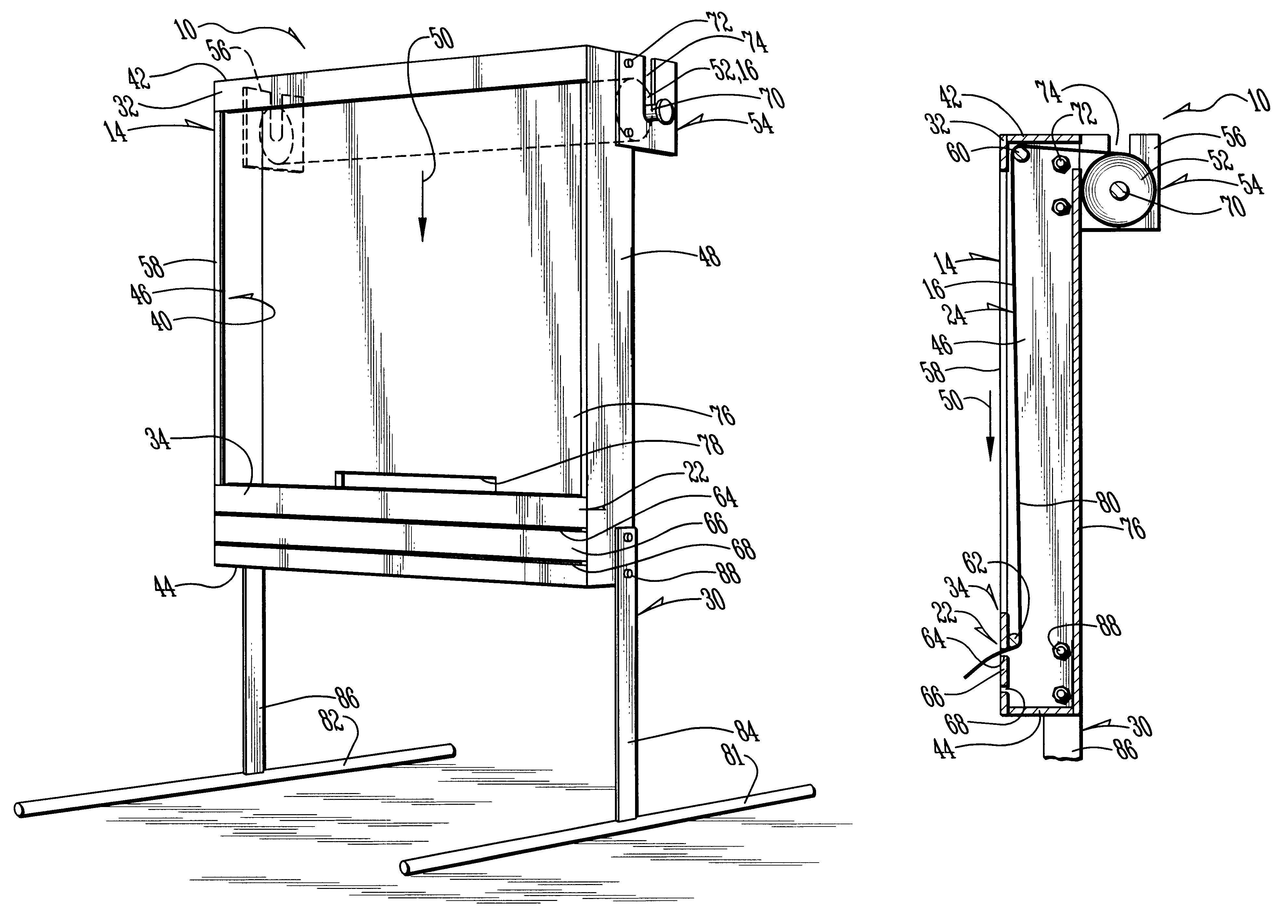
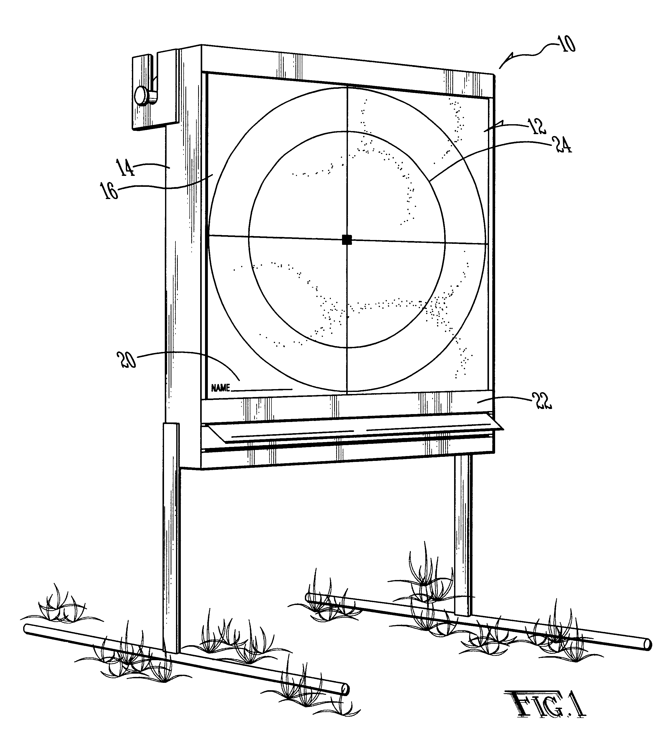
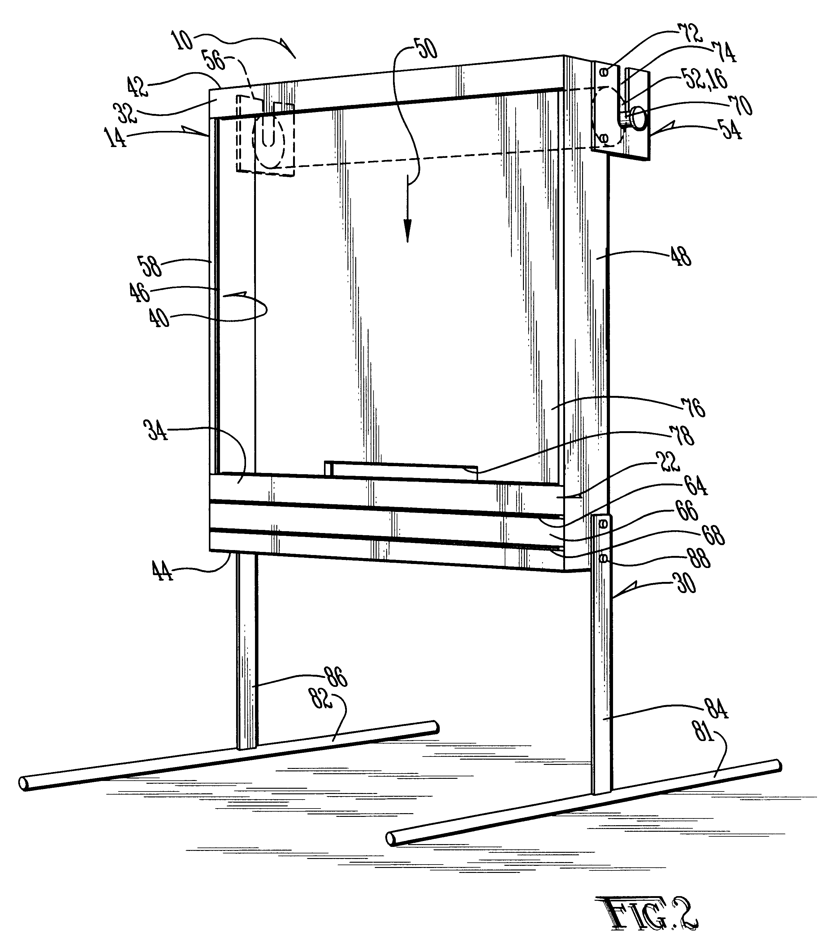
Referring to FIG. 1, a target assembly 10 embodying the present invention presents a target 12 toward a shooter in a manner that permits the shooter to accurately record a test firing and to record data pertinent to that test firing in a manner that will permit him to accurately analyze the results of the test firing.

Target assembly 10 includes a frame assembly 14 which supports a roll of target-containing paper 16 in an orientation with respect to a shooter that maintains the target 12 in a proper orientation throughout the test. That is, wind does not cause the target to move, and impact between the projectiles and the target does not skew the target whereby holes made in the target are precise and accurately located. Still further, target-containing paper 16, and hence target 12, is formed of a material that puncture...


PUM


Abstract

A target assembly includes special paper on which a target is imprinted and which is stored on a feeder roll in a frame and which is moved past a target area in the frame to either a take-up roll or to an exit slot. If the paper passes through the exit slot, it can be moved past a cutting slot and cut off using a knife or the like. The paper is a special rosin sized sheathing, such as forty pound wax paper, which retains the desired orientation during a target shoot, as well as makes clean, precise holes when impacted by shot whereby a precise record of a shot is made. An area on the paper adjacent to each target can be used to record data pertinent to the shoot whereby a firearm can be sighted in or a load adjusted.

Description

The present invention relates to the general art of firearms, and to the particular field of targets for firearms.Most, if not all, firearms should be sighted in in order to obtain the most accurate results. Sighting in generally requires aiming the firearm at a target using the sighting system on the firearm then firing at the target. The difference between the targeted location and the location actually hit is used to correct the aiming system of the firearm.This same system can be used to control loading of ammunition. The ammunition loading parameters are altered until a desired result is obtained. The actual versus the desired results are measured by firing at a target and recording the parameters of the load.While the art contains many examples of targets, the inventor is not aware of any targets that are specific to sighting in a firearm or loading ammunition, such as shotgun shells.Therefore, there is a need for a target that can be used specifically for sighting in a firear...

Claims


Application Information

Patent Timeline
Patent Type & Authority Patents(United States)
IPC IPC(8): F41J7/00
CPCF41J7/00F41J1/10
Inventor BAKER, JON ELLIS
Owner BAKER JON ELLIS
Why Eureka
Try Eureka