Lens holding frame for securing lens element to lens base

a technology for holding frames and lenses, applied in the field of lens holding frames for securing lens elements to lens bases, can solve the problems of inability to reduce the space for securing the mechanism, the number of parts is relatively high, and the above-described known method has a problem

Inactive Publication Date: 2003-04-08
FUJI PHOTO OPTICAL CO LTD
View PDF7 Cites 45 Cited by
  • Summary
  • Abstract
  • Description
  • Claims
  • Application Information

AI Technical Summary

Benefits of technology

The holding frame body further includes a flange formed on a periphery of the barrel portion, having the arm portions protruded therefrom. Plural arc-shaped slits are formed between the barrel portion and the flange, positioned to correspond to the arm portions, for facilitating deformation of the arm portions with resiliency.

Problems solved by technology

However, the above-described known method has a problem.
Therefore, the total number of parts is relatively high and cannot be low for the size reduction.
A space for securing the mechanism cannot be reduced.

Method used


Image

  • Lens holding frame for securing lens element to lens base
  • Lens holding frame for securing lens element to lens base
  • Lens holding frame for securing lens element to lens base

Examples


Embodiment Construction

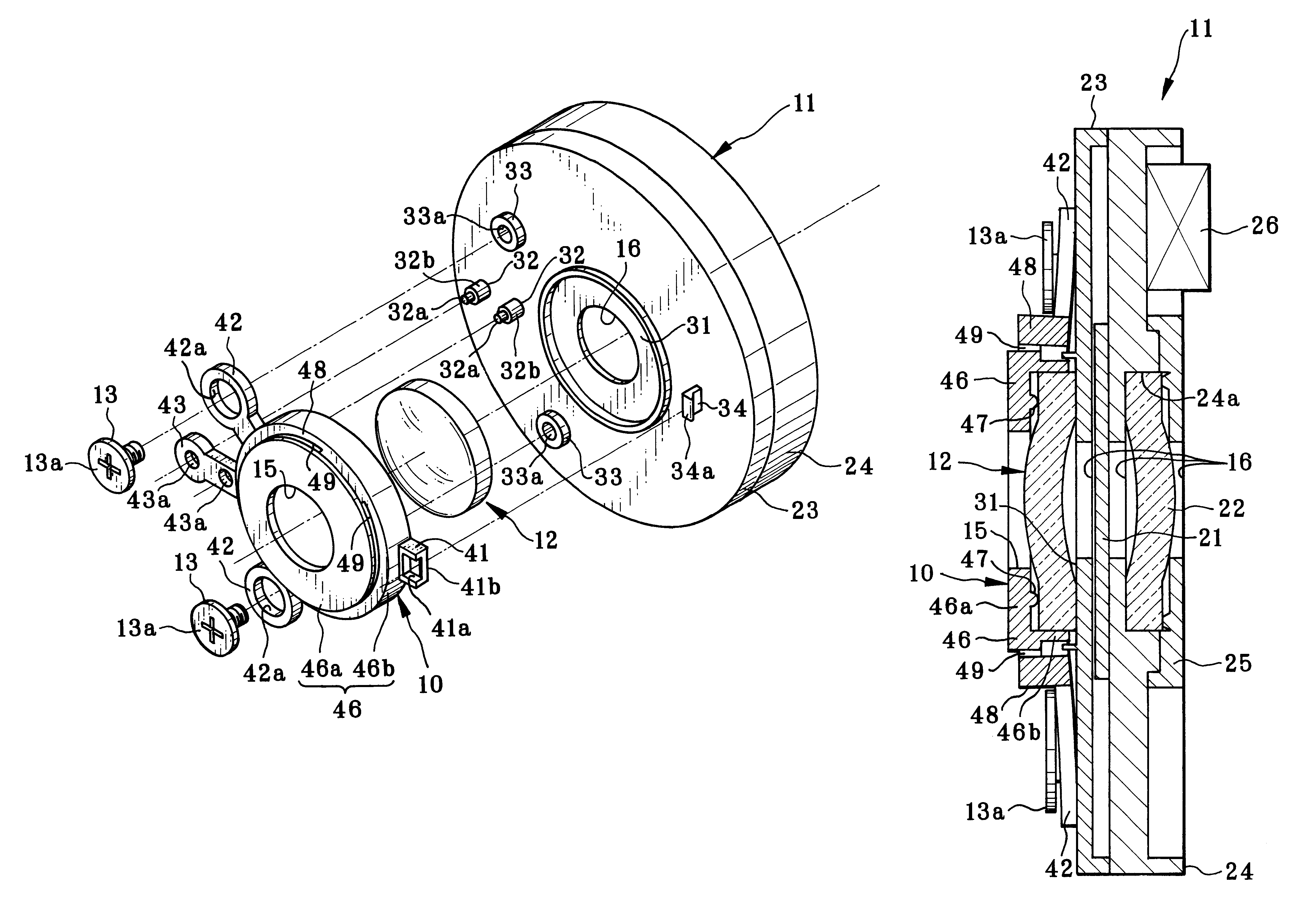
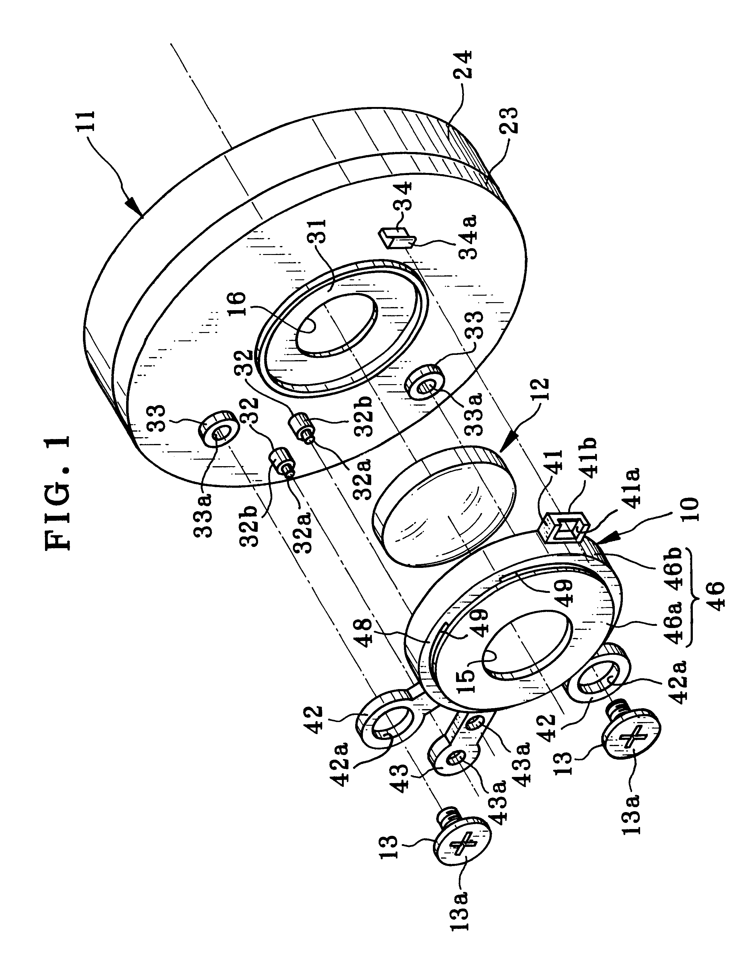
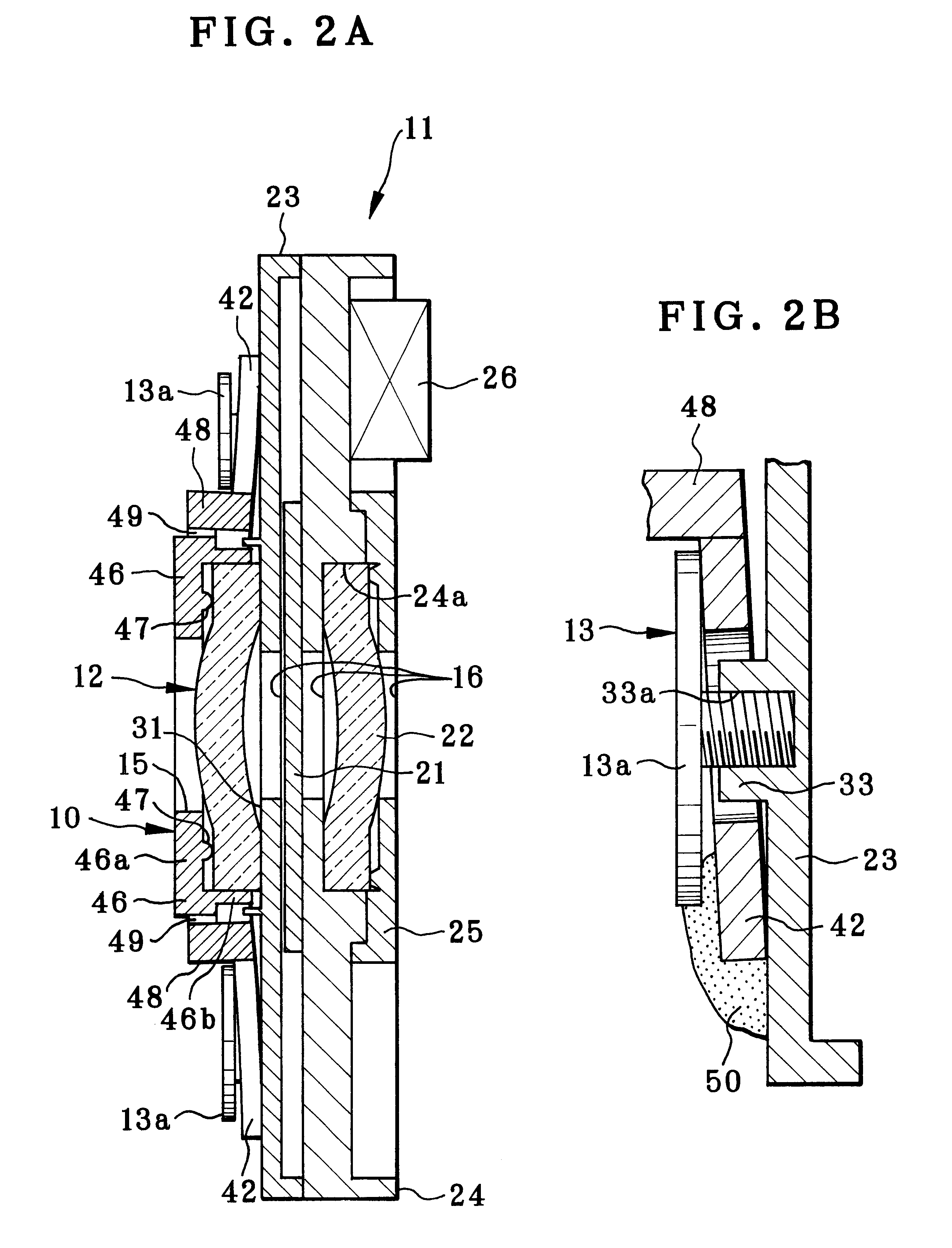
In FIGS. 1 and 2A, a lens holding frame 10 of a lens holder of the invention is illustrated. A first lens element 12 is supported on a shutter incorporated lens base 11 or a plate of a shutter unit. The lens holding frame 10 retains the first lens element 12 on the lens base 11. A lens barrel (not shown) is incorporated in a camera in a manner extendable in an optical axis direction. The lens holding frame 10 is fixedly mounted in the lens barrel. Movement of the lens barrel is for purposes of zooming and focusing. The lens barrel is so moved as to set a taking lens in stepwise positions with preset focal lengths, and to set the taking lens in focus. Note that the lens holding frame 10 of the invention constitutes a variator lens group among plural lens groups (not shown) as a zoom lens system. However, the lens holding frame 10 may constitute a focusing lens group among plural lens groups (not shown) as taking lens system. Furthermore, it is possible to mount the lens holding frame...


PUM


Abstract

A taking lens of a camera includes first and second lens elements. A lens holding frame retains the first lens element on a lens base or a front surface of a shutter unit. In the lens holding frame, a holding frame body is disposed in front of the first lens element. Arm portions are formed to project from a periphery of the holding frame body, have a distance to the lens base when in a free state, are bent resiliently by a retention pin or screws, and are secured to the lens base. Thus, the first lens element is squeezed tightly between the lens base and the holding frame body.

Description

1. Field of the InventionThe present invention relates to a lens holding frame for securing a lens element to a lens base. More particularly, the present invention relates to a lens holding frame for securing a lens element to a lens base in an optical instrument with sufficient tightness easily and exactly.2. Description Related to the Prior ArtA camera among various types of optical instruments includes a taking lens. To focus an image sharply, the lens must be properly controlled for a position. In the course of manufacturing the camera, it is necessary to position the taking lens in two manners, namely, in a direction along an optical axis of the taking lens, and also in directions vertical to the optical axis. It is known in the art to assemble the taking lens in a shutter unit which accommodates a shutter blade and a mechanism for driving the shutter blade. This is effective in miniaturizing the body of the camera.In FIG. 4, a shutter unit 61 of a known type is illustrated. A ...

Claims


Application Information

Patent Timeline
Patent Type & Authority Patents(United States)
IPC IPC(8): G02B7/02
CPCG02B7/02
Inventor SHOJI, MASAOOKUMURA, TETSUYA
Owner FUJI PHOTO OPTICAL CO LTD
Why Eureka
Try Eureka