Battery module

a battery module and module technology, applied in the field of batteries, can solve the problems of increased cost, increased safety venting, and reduced battery module li

Inactive Publication Date: 2003-04-22
PANASONIC CORP +1
View PDF11 Cites 26 Cited by
  • Summary
  • Abstract
  • Description
  • Claims
  • Application Information

AI Technical Summary

Benefits of technology

A battery module according to the present invention comprises an integrated battery case that is constituted by coupling together a plurality of cell cases into an integral body; and an integral lid member for closing open ends of the plurality of cell cases, wherein communicating paths are provided for communicating a predetermined number of neighboring cell cases with one another. Because the insides of the cell cases are mutually communicated through the communicating paths, the internal pressure in the cell cases becomes equal and gas that is generated in those cells whose deterioration is most advanced is absorbed by other cells, thereby suppressing the progress of oxidation deterioration of the most deteriorated cell and ensuring good balance in the internal pressure and the progress of deterioration between various cells, whereby the lifetime of the battery module is increased.
Furthermore, by making the thickness of shorter side walls between adjacent cell cases in the integrated battery case smaller than the thickness of outer side walls of the two cell cases located at either end of the battery module, the volume density of the battery module as a whole can be increased and the connection resistance between the cells can be lowered.

Problems solved by technology

However, in this conventional battery module, because the plurality of cells 41 are completely separate and sealed from each other, there was the following problem.
As a result, the balance of the condition of the electrode plates of the cells 41 in the battery module is disturbed, and inconveniences such as overcharging and over-discharging occur in some of the cells 41, which leads to a decrease in the lifetime of the battery module.
Moreover, safety vents 45 for releasing gas to the outside when the internal pressure in the cells 41 exceeds a certain value have to be provided for each of the cells 41, so that there was the problem that the number of safety vents 45 to be installed is large and the costs are high.

Method used


Image

  • Battery module
  • Battery module
  • Battery module

Examples


first embodiment

A battery module according to the present invention will be hereinafter described with reference to FIGS. 1 to 6.

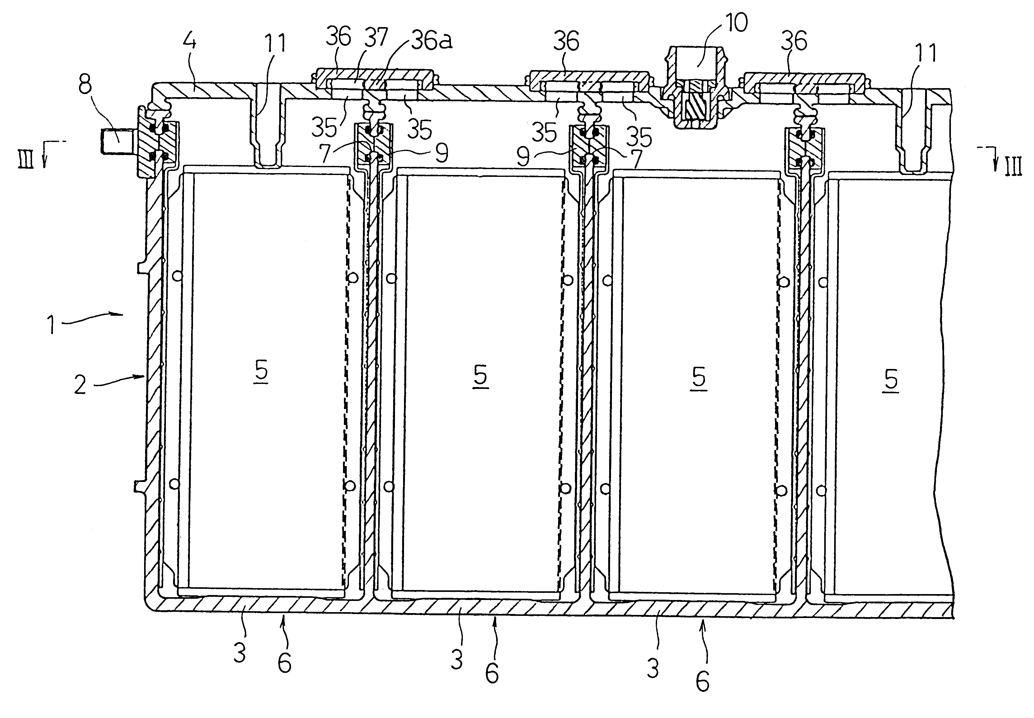
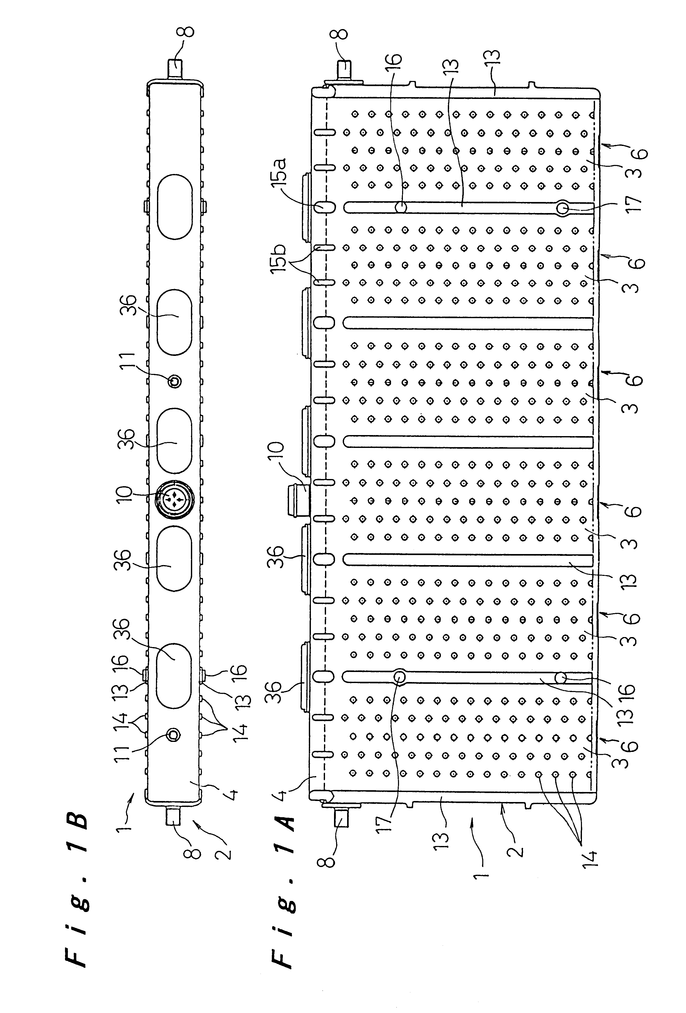
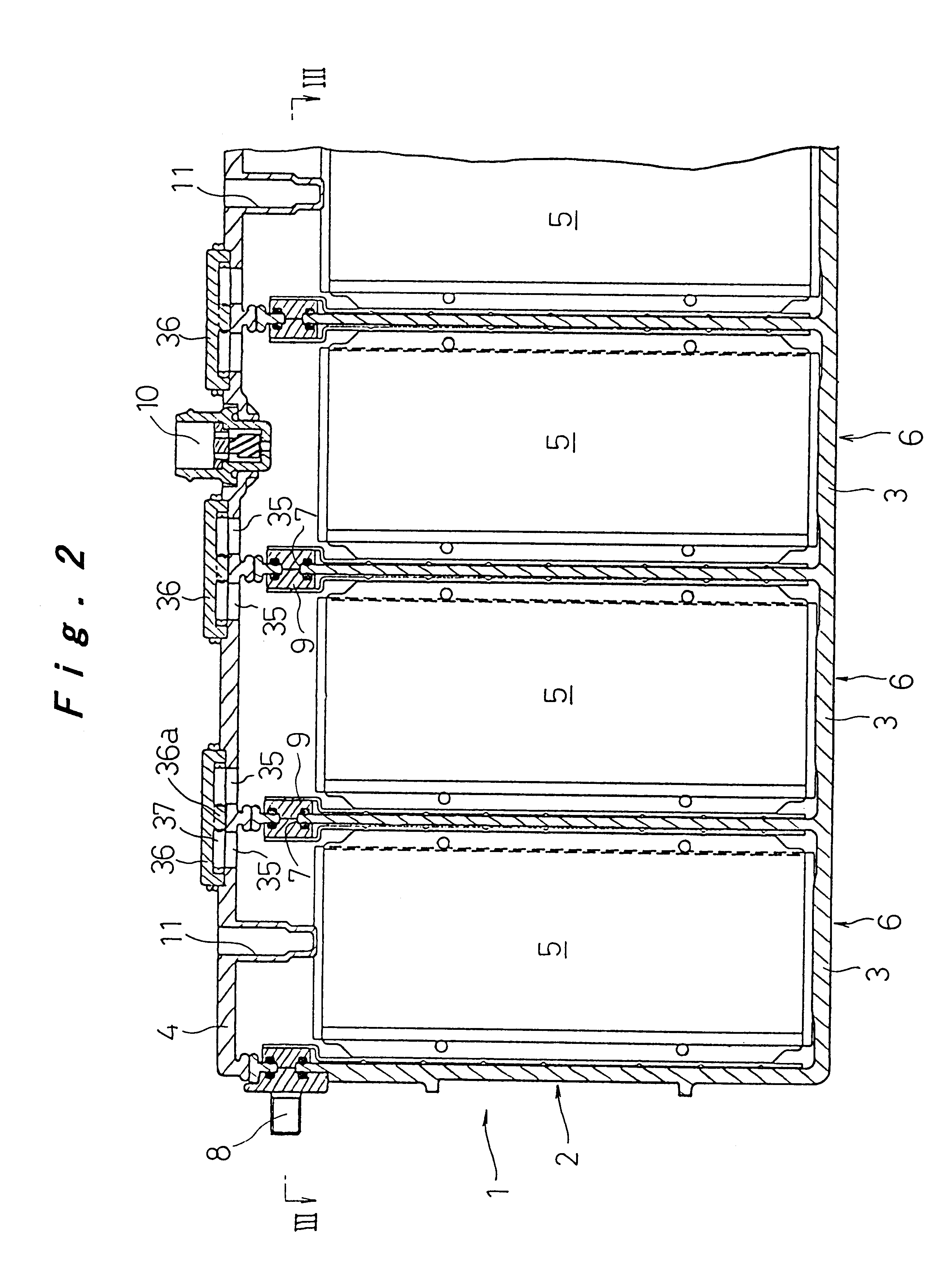
The battery module 1 of this embodiment constitutes a nickel metal hydride battery, which is suitable for use as a drive power source for an electric vehicle. As shown in FIGS. 1 to 3, it includes an integrated battery case 2 made by coupling together into an integral body a plurality (six in the example shown in the drawing) of cell cases 3, which are formed in a prismatic fashion with short side walls, long side walls, and open top ends, their short side walls being mutually integrated. The open top ends of the cell cases 3 are closed by an integrated lid member 4.

As will be explained in detail below, electrode plate groups 5 of a large number of negative plates and positive plates that are layered in the direction of the short side walls in parallel to the long side wall of the cell cases 3 with intervening separators are accommodated in the cell cases 3 together with ...

second embodiment

Next, a battery module according to the present invention will be described with reference to FIGS. 7 and 8. It should be noted that, in the description of the following embodiments, structural elements that are identical to those in the above embodiment are denoted at the same reference numerals, and only differing aspects will be explained.

In the first embodiment, an example has been explained, in which the collector plates 21, 22 of neighboring cells 6, 6 are connected with connection fittings 9 made of a pair of frame fittings 25. In this embodiment, cells 6 are constituted by accommodating, together with electrolyte, electrode plate groups 5 having collector plates 31, 32 of negative plates and positive plates at the opposite ends of the long lateral sides within prismatic cell cases 3 having short side walls and long side walls. Connection protrusions 33 that fit into the connection holes 7 formed in the upper edges of the short side walls of the cell cases 3 are protruded fro...


PUM

PropertyMeasurementUnit
heightaaaaaaaaaa
thicknessaaaaaaaaaa
power capacityaaaaaaaaaa

Abstract

An integrated battery case 2 is made by coupling together a plurality of cell cases 3 into an integral body, open ends of the cell cases 3 being closed integrally with a lid member 4. Communicating paths 37 for communicating a suitable number of neighboring cell cases 3 with one another are provided in the lid member 4, whereby the cell cases 3 have a uniform internal pressure.

Description

1. Technical Field of the InventionThe present invention relates to a battery module made by connecting a plurality of rechargeable batteries so as to obtain a necessary power capacity.2. Description of Related ArtFIG. 13 shows a conventional battery module made by connecting a plurality of cells and coupling them integrally so as to obtain a necessary power capacity. In this battery module, a plurality of cells 41 (41a to 41j) made of sealed alkaline rechargeable batteries as shown in FIG. 14 are arranged in a row with the long side walls of the cell cases 42 adjacent with each other. End plates 52 are placed against the outside of the cells 41a and 41j at the opposite ends, and the cells, together with the two end plates 52, 52, are bound together with binding strips 53, whereby the plurality of cells are coupled into an integral body.In the cells 41, an electrode plate group 47, or elements for electromotive force, made by laminating negative plates and positive plates with inter...

Claims


Application Information

Patent Timeline
Patent Type & Authority Patents(United States)
IPC IPC(8): H01M2/22H01M2/24H01M2/02H01M2/12H01M2/04H01M10/34H01M10/50H01M10/42H01M10/04H01M10/28H01M50/112H01M50/147H01M50/529
CPCH01M2/0242H01M2/0245H01M2/043H01M2/12H01M2/24H01M10/5004H01M10/5016H01M10/5032H01M10/5059Y02E60/124H01M10/345H01M10/625H01M10/647H01M10/6557H01M10/613Y02E60/10H01M50/112H01M50/258H01M50/147H01M50/30H01M50/529Y02P70/50
Inventor HAMADA, SHINJIINOUE, HIROSHIFUJIOKA, NORIYUKIIKOMA, MUNEHISA
Owner PANASONIC CORP
Why Eureka
Try Eureka