X-ray collimator and method of manufacturing an x-ray collimator

a collimator and collimator technology, applied in the field of radiography, can solve the problems of expensive machining methods, and achieve the effect of less expensive manufacturing and precise beam cross-section

Inactive Publication Date: 2003-04-29
ANLOGIC CORP (US)
View PDF16 Cites 45 Cited by
  • Summary
  • Abstract
  • Description
  • Claims
  • Application Information

AI Technical Summary

Benefits of technology

A collimator constructed in accordance with the present disclosure produces precise beam cross-sections, yet is less expensive to manufacture.

Problems solved by technology

If the collimator is made of a very hard material, such as tungsten or a tungsten carbide, then expensive machining methods such as wire electrical discharge machining must be used to manufacture the collimator.

Method used


Image

  • X-ray collimator and method of manufacturing an x-ray collimator
  • X-ray collimator and method of manufacturing an x-ray collimator
  • X-ray collimator and method of manufacturing an x-ray collimator

Examples


Embodiment Construction

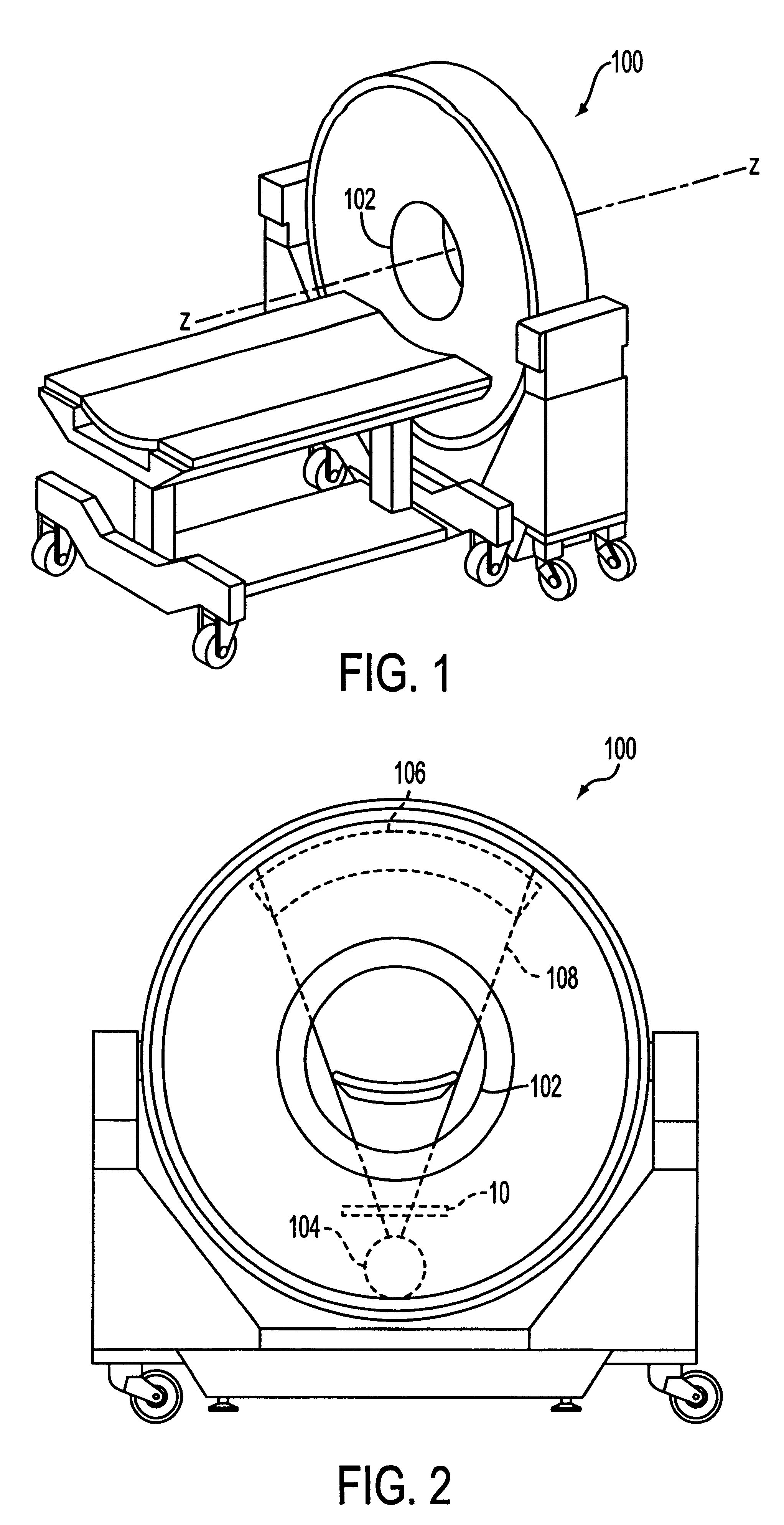
Referring first to FIGS. 1 and 2, in computed tomography, a patient (not shown) to be examined is positioned in a scan circle 102 of a computer tomography (CT) scanner 100, parallel with a z-axis, and between an x-ray source 104 and a rectangular detector array 106. The x-ray source then projects a beam of energy, or x-rays 108, through the patient, to the detector array. By rotating the x-ray source about the z-axis and relative to the patient, radiation is projected through a portion of the patient to the detector array from a many different directions around the patient. An image of the scanned portion of the patient then is constructed from data provided by the detector array.

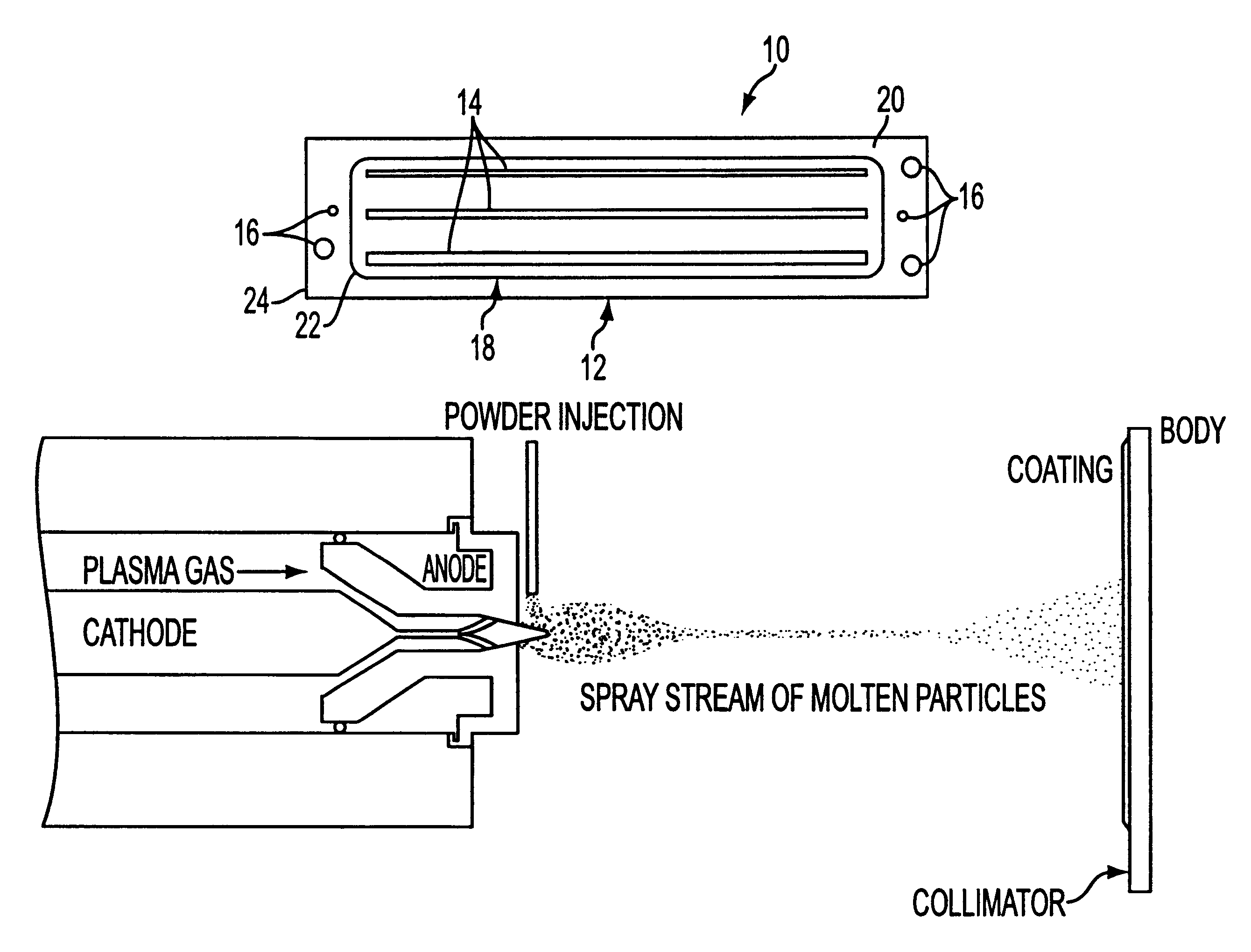
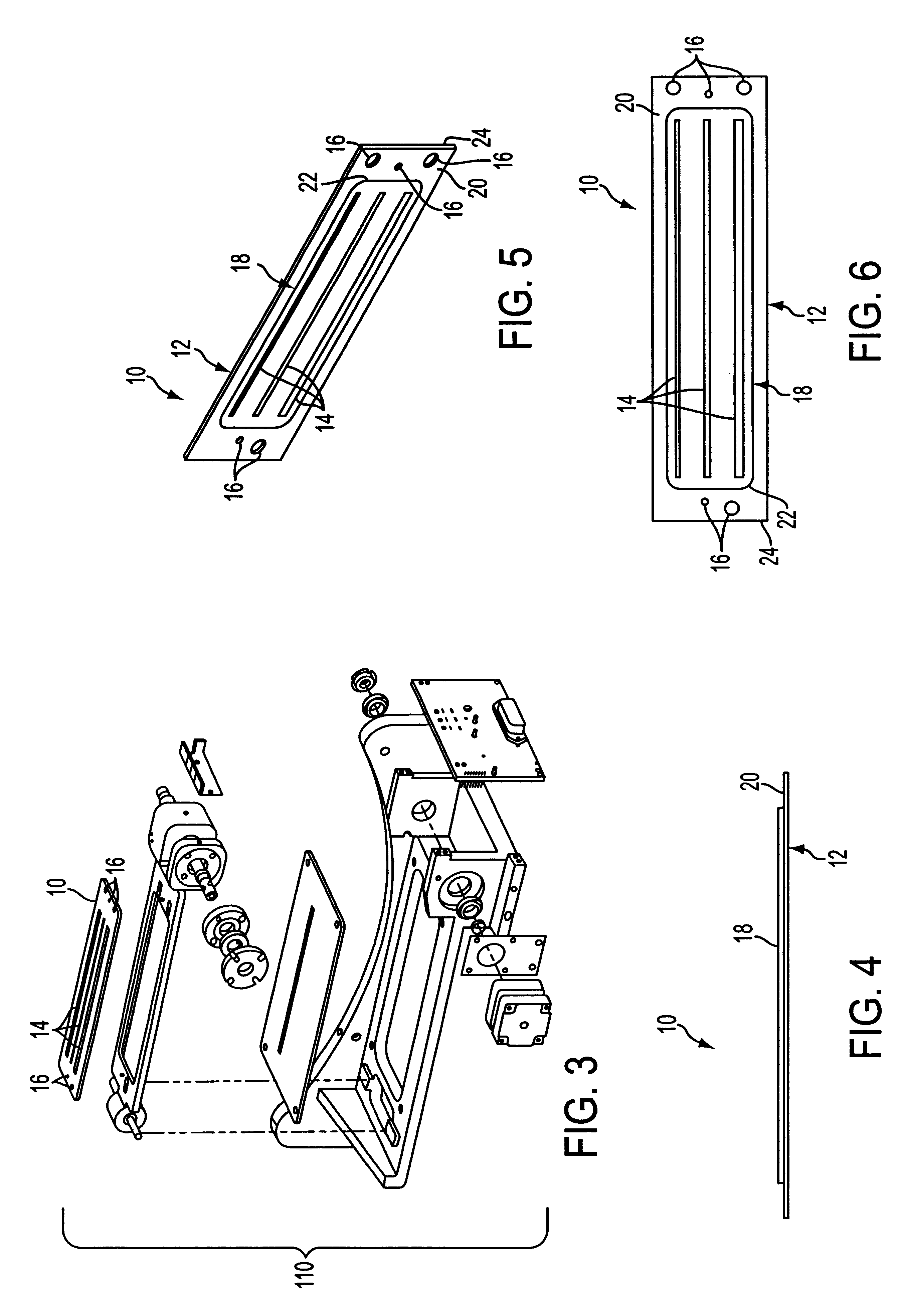
The scanner 100 of FIGS. 1 and 2 employs a collimator 10 for shaping the cross-section of the beam 108 into a rectangular shape that matches the rectangular detector array 106. The collimator 10 ensures that only a preferred row of the detector array 106 is irradiated by the beam 108 and so that a patient b...


PUM

PropertyMeasurementUnit
thicknessaaaaaaaaaa
distancesaaaaaaaaaa
computed tomographyaaaaaaaaaa

Abstract

A method of manufacturing a collimator including providing a plate-like body, coating a predetermined portion of a surface of the body with an x-ray absorbing material, and machining at least one collimating slit through the coating and the plate-like body. According to one exemplary embodiment, the coating is applied through a thermal spray process. According to another exemplary embodiment, wire electrical discharge machining (EDM) is used to machine the collimating slits. A collimator manufactured in accordance with the presently disclosed method produces precise energy beam cross-sections, yet is less expensive to manufacture.

Description

FIELD OF DISCLOSUREThe present disclosure relates to the field of radiography and, in particular, relates to computer tomography scanners. Even more particularly, the present disclosure relates to an x-ray collimator for use as part of a computer tomography scanner, and a method of manufacturing an x-ray collimator.BACKGROUND OF DISCLOSUREIn computed tomography, a patient to be examined is positioned in a scan circle of a computer tomography (CT) scanner. A shaped x-ray beam is then projected from an x-ray source through the scan circle and the patient, to an array of radiation detectors. By rotating the x-ray source and the collimator relative to the patient (about a z-axis of the scanner), radiation is projected through an imaged portion of the patient to the detectors from a multiplicity of directions. From data provided by the detectors, an image of the scanned portion of the patient is constructed.Within the x-ray source, an electron beam strikes a focal spot point or line on a...

Claims


Application Information

Patent Timeline
Patent Type & Authority Patents(United States)
IPC IPC(8): G21K1/02
CPCG21K1/02
Inventor TYBINKOWSKI, ANDREW P.SWAIN, RONALD E.DUFFY, MICHAEL J.
Owner ANLOGIC CORP (US)
Why Eureka
Try Eureka