Replaceable, self-contained expanded viewing light shield cartridge for welding helmet

a welding helmet and expansion technology, applied in the field of optical filters, can solve the problems of limited liquid crystal display sizes, welders are prone to eye, face and neck injuries, and welding helmets cannot be seen with such filters in place,

Inactive Publication Date: 2003-05-06
WALTER SURFACE TECH
View PDF14 Cites 42 Cited by
  • Summary
  • Abstract
  • Description
  • Claims
  • Application Information

AI Technical Summary

Benefits of technology

Still another object of this invention is to provide an electronic quick change cartridge for a welding helmet that provides an expanded viewing area when an arc exists during a welding operation.
Yet another object of this invention is to provide a quick change cartridge for a welding helmet that provides expanded viewing during welding and incorporates the advantages of an LCD device.
In accordance with this invention, an optical filter assembly for protecting eyes in an environment having a switchable intense light source includes a base, a filter, a control circuit and an opaque filler. The base has an aperture therethrough, a cavity spaced from the aperture and a channel interconnecting the aperture and the cavity, and the base is formed of a material having a fixed light transmission characteristic. The filter, disposed in the aperture, switches between a first optical density corresponding to the fixed light transmission characteristic of the base and a second, reduced optical density. The control circuit, that mounts in the cavity and connects to the filter through the channel, controls the optical density of the filter in response to the presence of the intense light. The opaque filler is in the cavity and the channel. An individual has substantially uniform vision through the filter and the base in the presence of the intense light and through the filter in the absence of the intense light.
In accordance with another aspect of this invention, a replaceable optical cartridge for insertion in a welding helmet protects a welder's eyes from the intense light of a welding arc while enabling the welder visibility therethrough in the absence of the arc. The cartridge includes a base, a liquid crystal display filter, a control circuit and an opaque filler. The base has an aperture therethrough, a cavity spaced from the aperture and a channel interconnecting the cavity and the channel, and the base, has a predetermined shade number. The liquid crystal display filter mounts in the aperture and responds to a control signal by switching operating between a first light transmission characteristic corresponding to the predetermined shade number and a second, greater light transmission characteristic. The control circuit mounts in the cavity and connects to the filter through the channel for controlling the operation of the filter in response to the presence of an arc. The opaque filler is in the cavity and the channel. With this structure a welder has substantially uniform vision through the filter and the base in the presence of the arc and vision through the filter in the absence of the arc.

Problems solved by technology

However, a welder can not see a work piece with such a filter in place unless an arc is present or the work piece is brightly lit.
Consequently welders are prone to suffer eye, face and neck injuries.
However, liquid crystal displays have limited sizes and are not available to a size corresponding to the size of passive filters.
As a result auto-darkening welding filters can severely restrict a welder's field of view during the welding process.
However, viewing is limited to only that area of the LCD when an arc is struck.
However, prior art welding helmets with LCD devices have only limited viewing through a portion of a total viewing area for a comparable sized passive filter.
Thus while passive filters can provide a large viewing area, they do not incorporate the dual density and attenuation advantages of an LCD device.

Method used


Image

  • Replaceable, self-contained expanded viewing light shield cartridge for welding helmet
  • Replaceable, self-contained expanded viewing light shield cartridge for welding helmet
  • Replaceable, self-contained expanded viewing light shield cartridge for welding helmet

Examples


Embodiment Construction

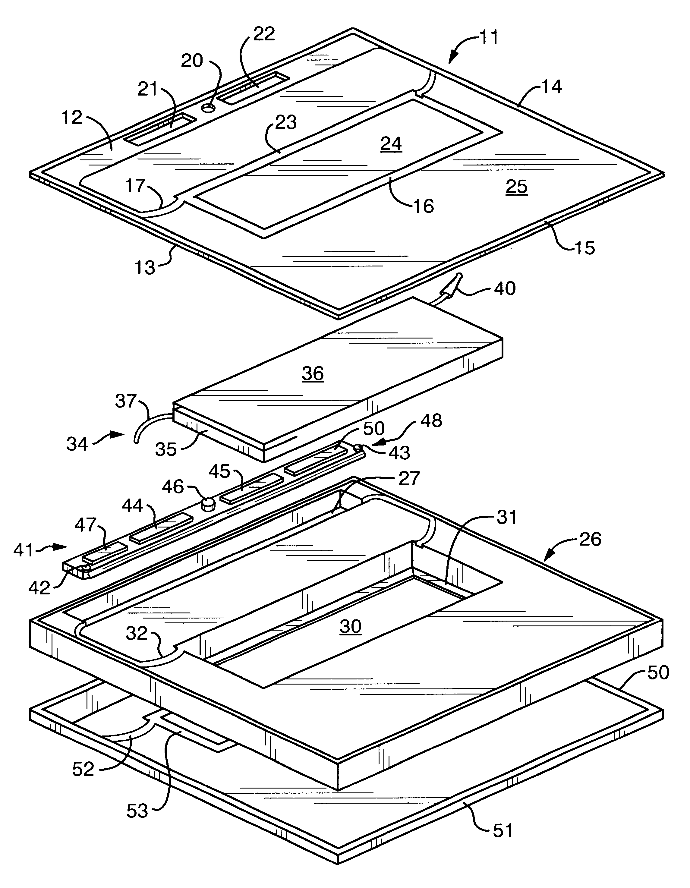
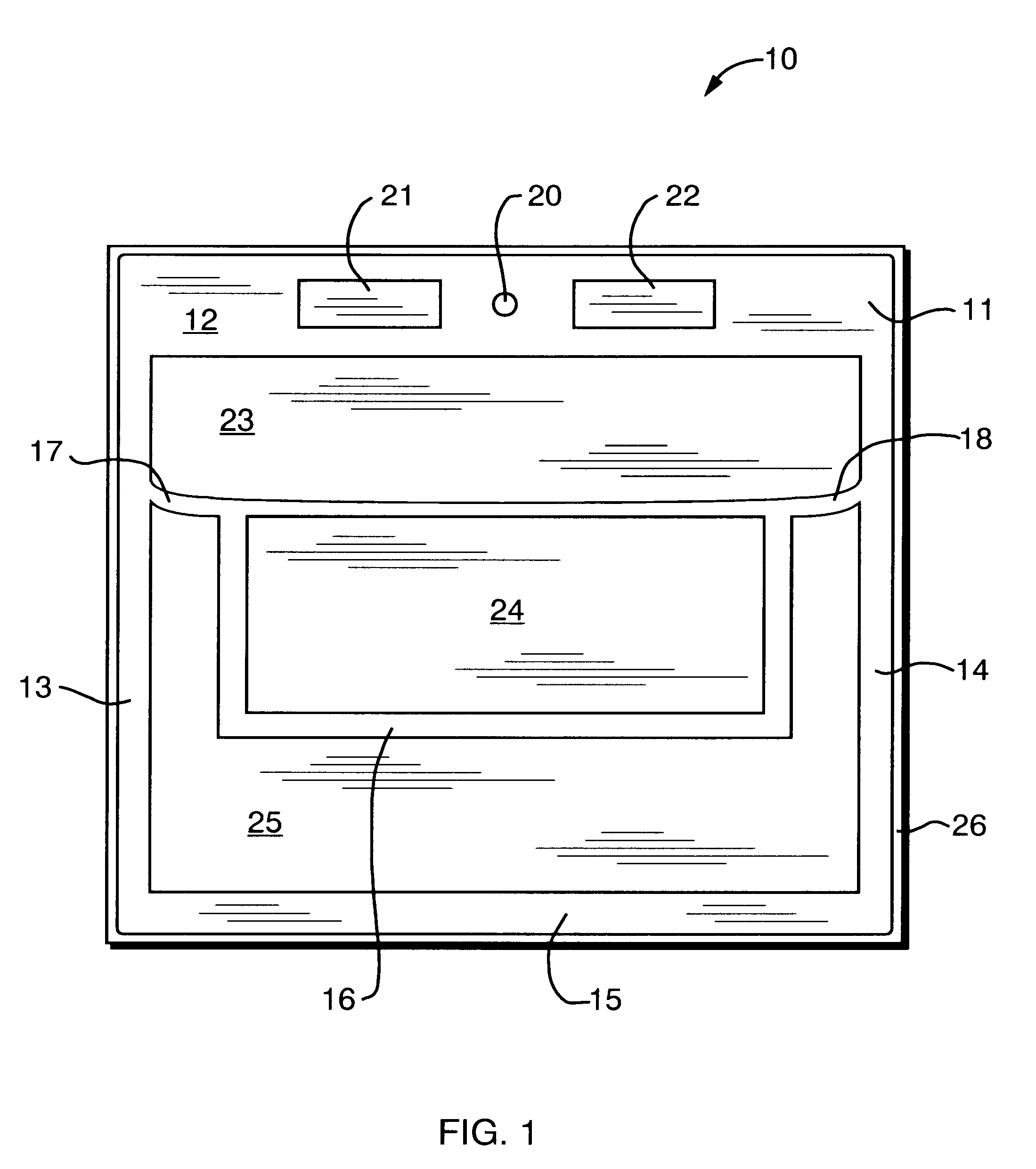
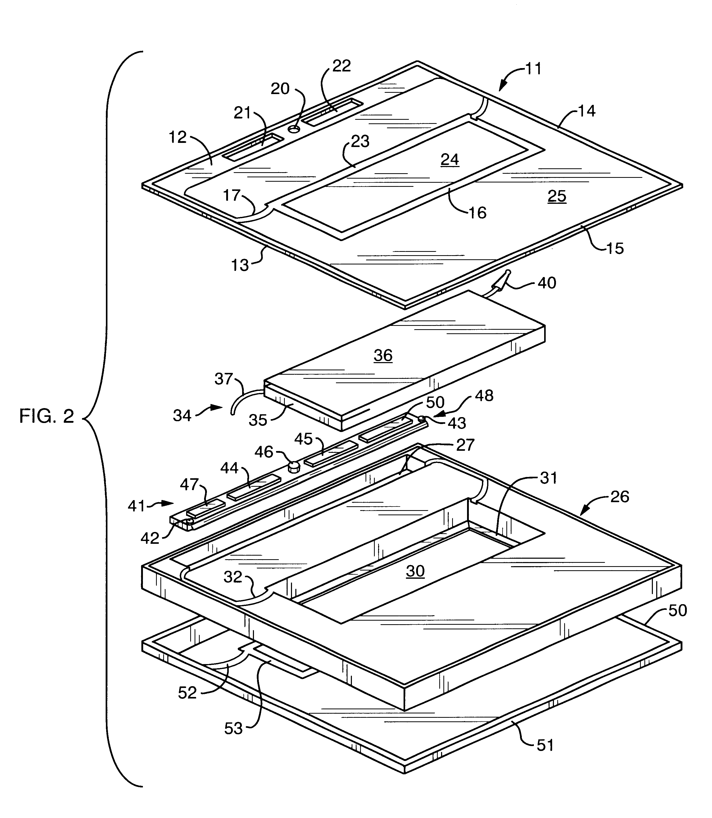
Referring to the FIGS. 1 and 2, an electronic quick change cartridge 10 constructed in accordance with one aspect of this invention includes three layers and five components. A first layer that forms an exterior front surface of the cartridge comprises an optical mask 11 with a pattern of opaque and transparent portions. The optical mask 11 could be made of glass, plastic or other material to provide a reasonably surface abrasion resistant exterior surface. The opaque portions include an upper opaque cross-section 12, edge opaque sections 13 and 14, an end opaque section 15, an opaque portion 16 in the form of an open rectangle located in the middle portion of the mask 11 and two extensions 17 and 18 from one side of the mask to the corresponding edge opaque portions 13 and 14.

The optical mask 11 also contains three transparent areas or portions including a centrally located circular opening 20 and two rectangular openings 21 and 22 on either side of the circular opening 20 all in t...


PUM


Abstract

An electronic quick change cartridge for a welding helmet. The cartridge base is formed of an optically dense polycarbonate or like material that acts as a passive filter to provide eye protection during the welding process. A port in the base receives a variable density LCD cell and a cavity formed in the base receives the electronics for driving the cell. Optical masks prevent light leakage through any interfaces of the structure. When low light levels are present, the welder views a work piece through an essentially transparent or slightly opaque LCD cell. When an arc is struck, the LCD cell darkens to a shade corresponding to the shade of the surrounding polycarbonate material. The welder then can view the work piece through the LCD cell and all the optically unobstructed portions of the polycarbonate base surrounding the LCD cell thereby to have an expanded viewing area during the actual welding operation.

Description

1. Field of the InventionThis invention generally relates optical filters to provide eye protection from an intense light source and more specifically to a replaceable, quick connect cartridge for use in welding helmets.2. Description of Related ArtWelding helmets have been used for a significant period of time to protect a welder's eyes during the welding process. Protection is afforded by placing a relatively opaque filter between the welder's eyes and an arc that is an intense light source. Early filter designs, still in use, rely upon fixed optical density filters or passive filters. These passive filters have the advantage of presenting a large viewing area. However, a welder can not see a work piece with such a filter in place unless an arc is present or the work piece is brightly lit. Although proper welding procedures and techniques involve placing the welding tool proximate the work piece, lowering the face plate then striking the arc, in practice an alternative procedure h...

Claims


Application Information

Patent Timeline
Patent Type & Authority Patents(United States)
IPC IPC(8): A61F9/04A61F9/06
CPCA61F9/067Y10S2/906
Inventor MARTIN, EDWARD L.EDGAR, FREDERICK P.
Owner WALTER SURFACE TECH
Why Eureka
Try Eureka