Cable with parallel wires for building work structure, anchoring for said cable, and anchoring method

a technology of building work structure and parallel wires, which is applied in the direction of cable-stayed bridges, bridges, transportation and packaging, etc., can solve the problems of differential elongation between the central wire and the peripheral wires, the fatigue behavior of the strand as defined hereinabove is not as good as that of the wire, and the production of twisted strands or twists requires a special twisting operation,

Inactive Publication Date: 2003-05-13
FREYSSINET INT STUP
View PDF32 Cites 19 Cited by
  • Summary
  • Abstract
  • Description
  • Claims
  • Application Information

AI Technical Summary

Benefits of technology

By virtue of this arrangement, the cohesion of the reinforcement obtained is preserved while the mechanical properties of the reinforcement are equivalent or equal to those of a constituent wire.

Problems solved by technology

However, producing the twisted strand or twist entails a special twisting operation which is expensive.
In addition, this operation gives rise to differential elongation between the central wire and the peripheral wires.
Furthermore, the fatigue behavior of a strand as defined hereinabove is not as good as that of the wire of which it is made because the differential elongation between the peripheral wires and the central wire gives rise to differential movements with radial pressure and therefore to friction between the wires which is not really favorable in terms or fatigue.
An additional drawback lies in the work hardening that results from the twisting, which creates a stiff steel with residual internal tensions making it less ductile and therefore susceptible to creep or to relaxation, according to the type of loading.
This operation leads to additional cost and may be tricky because it demands a great deal of precision on the temperature when the wires are galvanized wires.
This is because the melting point of zinc is not to be exceeded while at the same time not reducing the temperature too far as this would render the operation ineffective.
This operation, because of the need to untwist the wires and then twist them again, leads to further work hardening by deformation of the peripheral wires, which reduces the ductility of the strand.

Method used


Image

  • Cable with parallel wires for building work structure, anchoring for said cable, and anchoring method
  • Cable with parallel wires for building work structure, anchoring for said cable, and anchoring method
  • Cable with parallel wires for building work structure, anchoring for said cable, and anchoring method

Examples


first embodiment

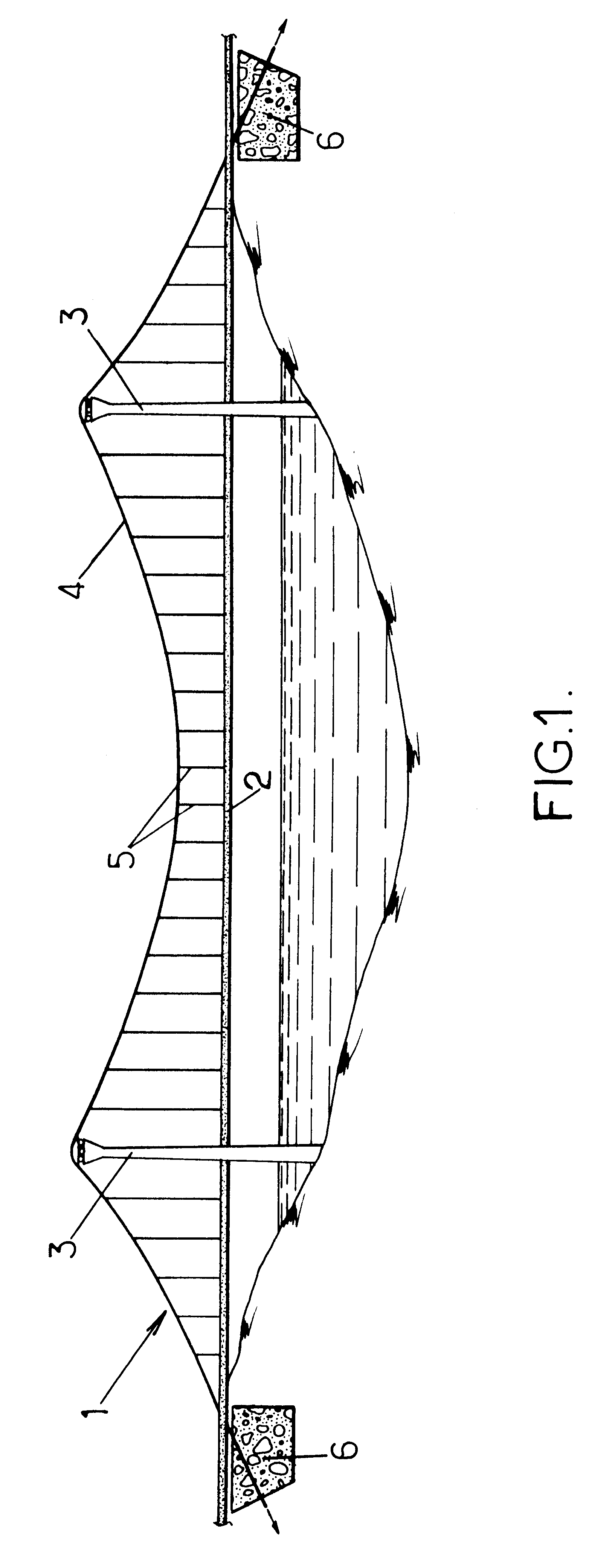
Each suspension cable 3 consists of one or more reinforcements 10 according to the invention, like the one depicted in FIG. 2.

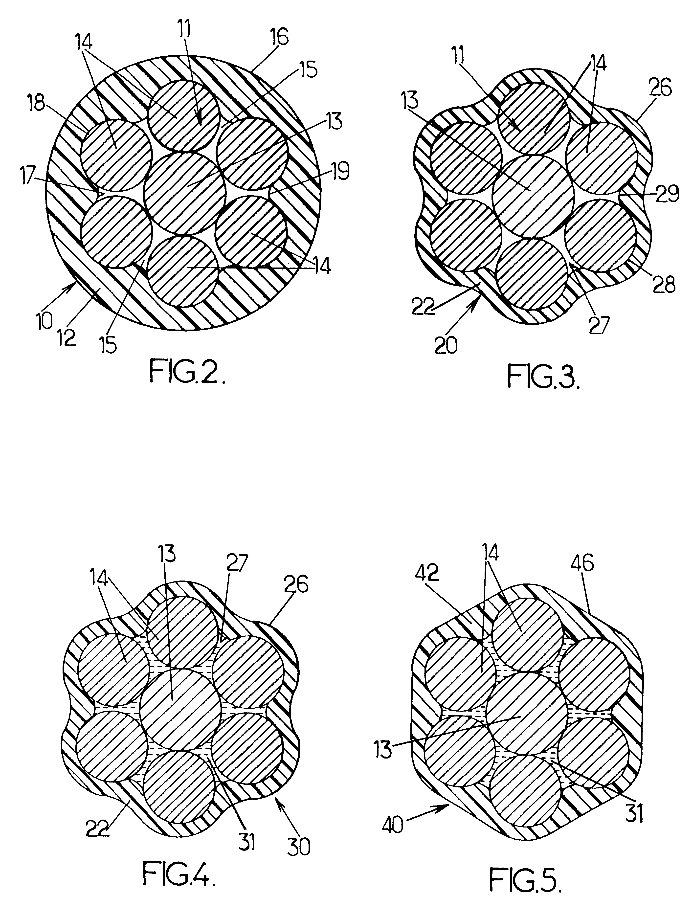
Each reinforcement 10 consists of a collection of solid wires 11 which form a bundle enveloped in a sheath 12. The reinforcement 10 thus formed is also known as a strand, and may be combined with other strands to form the cable 4. It is thus understood that the term "reinforcement" denotes a flexible assembly which can be wound so that it can be stored and transported, and is then unwound to be installed in a building work.

Within a strand, the wires 11 are generally seven in number and comprise a central wire 13 around which six peripheral wires 14 are arranged. The wires 13 and 14 run parallel to each other and are, for example, made of steel.

The wires 13 and 14 are in mutual contact along their generatrix. Only the central wire 13 is in contact with all the other peripheral wires 14. The peripheral wires 14 are separated one from the next and delimit groove...

second embodiment

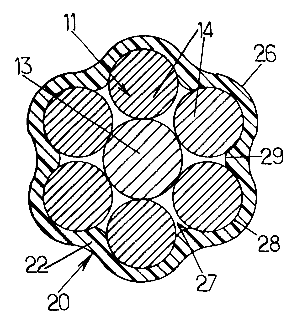
In a second embodiment, like the one depicted in FIG. 3, the reinforcement 20 can be distinguished from the reinforcement 10 only by the shape of the exterior wall of the sheath or sheath 22. This sheath has an exterior wall 26 and an interior wall 27 which, in cross section, are both of lobed shape.

The interior wall 27 is similar to the interior wall 17 of the sheath 12 of the first embodiment and has recesses 28 and projections 29. The exterior wall 26 has recesses and projections which correspond respectively with the projections and the recesses of the interior wall 27.

third embodiment

The reinforcement 30 of the third embodiment depicted in FIG. 4 differs from the reinforcement 20 previously described only in that the wires 13 and 14 are embedded in an elastomer matrix 31 such as polybutadiene or the like. This matrix occupies the gaps between the wires 13, 14. The elastomer 31 adheres to the wires, by surface adhesion, preferably, by chemical bonding with the sheath 22 in order to increase this adhesion. As an alternative, the matrix may be a lubricant such as wax or grease so as to reduce the friction between the wires and the sheath.


PUM

PropertyMeasurementUnit
temperatureaaaaaaaaaa
flexibleaaaaaaaaaa
circular shapeaaaaaaaaaa

Abstract

A reinforcement for a building works structure comprising an assembly of solid wires. The wires are mutually parallel to form a bundle and the reinforcement comprises a sheath made of plastic material enclosing the bundle and providing it with cohesion.

Description

The present invention relates to the field of reinforcements used in building work structures.The invention is aimed in particular, although not exclusively, among these structures, at those intended to equip cable stayed bridges, suspension bridges or the like. The reinforcements habitually encountered in such structures comprise a certain number of wires.In known embodiments of the reinforcements of the kind in question, the various constituent wires are (generally twisted around a central wire. This arrangement is used to produce a strand, also known as a twist, made from wires of small diameter. The mechanical properties of the strand obtained are better than those of a single-wire strand in which the cross section of the single wire is equivalent to that of said strand.DESCRIPTION OF THE RELATED ARTTwisting the peripheral wires around a central wire secures the wires of the strand or twist together and reduces the flexural inertia of the assembly. A reinforcement unit is thus o...

Claims


Application Information

Patent Timeline
Patent Type & Authority Patents(United States)
IPC IPC(8): E01D19/16E01D19/00E04C5/08E04C5/00E01D11/02E01D11/04E01D11/00E01D101/40
CPCD07B1/068D07B5/002D07B1/165E01D19/16E04C5/08D07B1/162D07B2201/2023D07B2201/2033D07B2201/2044D07B2201/2046D07B2201/206D07B2201/2062D07B2201/2065D07B2201/2073D07B2201/2085D07B2201/2086D07B2205/201D07B2205/2075D07B2501/2023Y10T428/2973Y10T428/2933Y10T428/2929D07B2801/16D07B2801/18D07B2801/24
Inventor STUBLER, JEROMELADRET, PATRICKPERCHERON, JEAN-CLAUDE
Owner FREYSSINET INT STUP
Why Eureka
Try Eureka