Eliminating air pockets under a polishing pad

a technology of air pockets and polishing pads, which is applied in the direction of grinding machines, manufacturing tools, lapping machines, etc., can solve the problems of air bubbles getting trapped between the adhesive and the platen, virtually impossible to eliminate trapped air, and raised areas or bulges on the polishing surface of the polishing pad

Inactive Publication Date: 2003-05-13
ROHM & HAAS ELECTRONICS MATERIALS CMP HLDG INC
View PDF14 Cites 39 Cited by
  • Summary
  • Abstract
  • Description
  • Claims
  • Application Information

AI Technical Summary

Problems solved by technology

As the polishing pad is placed on the platen, bubbles of air tend to get trapped between the adhesive and the platen.
This is a particular problem with large diameter pads, such as a typical 91 cm diameter pad, in which it is virtually impossible to eliminate trapped air.
Any trapped air will distend the relatively thin pad material, thereby causing raised areas or bulges in the polishing surface of the polishing pad.
Forcing the air bubbles out from under the pad with a roller is not effective.
This is a time-consuming process, and some small bulges often go undetected and remain in the polishing surface.
Any bulges in the polishing surface will generate non-uniformities on the polished surface of the workpiece (i.e., a semiconductor wafer), thereby causing defects in the polished surface.
The larger diameter polishing pads pose more of a problem since it is almost impossible to manually remove trapped air from under these pads.

Method used


Image

  • Eliminating air pockets under a polishing pad
  • Eliminating air pockets under a polishing pad

Examples


Embodiment Construction

91 cm. diameter IC 1400 pad manufactured by Rodel Inc., Newark, Del., which is an IC 1000 pad manufactured by Rodel having a backing layer of a closed cell urethane foam sub pad, was mounted onto a standard platen of a conventional polishing machine. Air bubbles under the pad were formed during the mounting process and could not be removed using conventional means such as a pad mounting disc and could only be removed by punching a hole in the pad to release the entrapped air.

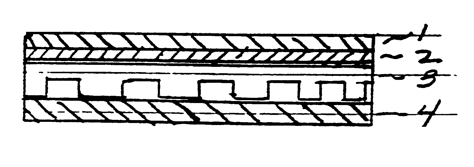
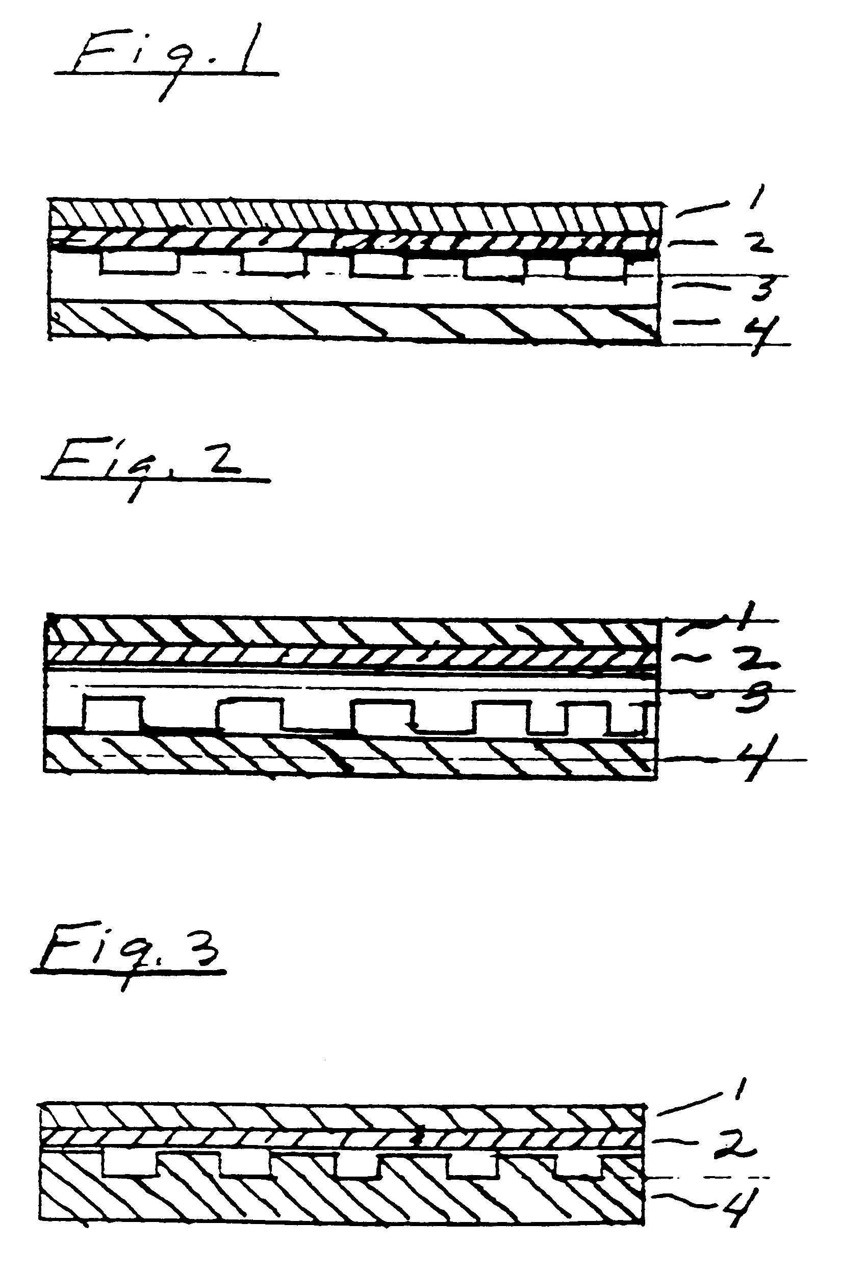
A second 91 cm diameter IC 1400 pad was mounted onto a standard platen of a polishing machine. A semi rigid base material was positioned between the pad and the polishing platen such that the grooves in the base material faced the back of the pad. This base material, which is an epoxy impregnated fiberglass, has a thickness of 1.27 mm, has machined grooves in the x and y directions at a 90 degree angles in which the grooves are 0.254 mm. wide, 0.81 mm deep and at a 25.4 mm pitch. Any entrapped air bubbles were r...


PUM

PropertyMeasurementUnit
widthaaaaaaaaaa
anglesaaaaaaaaaa
diameteraaaaaaaaaa

Abstract

A polishing pad assembly is provided that is useful for the chemical mechanical polishing of glass and electrical devices such as semiconductor wafers that comprises a polish pad and a semi-rigid base material firmly adhered to the polishing pad for positioning on a polishing platen of a polishing machine; wherein the semi-rigid base material has a modulus of rigidity of 0.01-50 GPa (GigaPascals) determined according to ASTM D 790, a thickness of 0.25-15.0 mm, and a grooved surface having a pitch of 5-100 mm and the grooves have a width of 0.025-2.5 mm and a depth of 0.1-2.5 mm.

Description

This invention relates to a polishing pad assembly that is useful for chemical-mechanical polishing (CMP) in which air bubbles or pockets of air that form between the polishing pad and a polishing platen are minimized or eliminated.DESCRIPTION OF RELATED ARTSemiconductor wafers having integrated circuits fabricated thereon must be polished to provide a very smooth and flat wafer surface which, in some cases, may vary from a given plane by as little as a fraction of a micron. Such polishing is usually accomplished in a chemical-mechanical polishing (CMP) operation that utilizes a chemically active slurry that is buffed against the wafer surface by a polishing pad.Typical pads used in CMP polishing are shown in the following patents: Cook et al. U.S. Pat. No. 6,022,264 issued Feb. 8, 2000; Roberts et al. U.S. Pat. No. 6,022,268 issued Feb. 8, 2000; Roberts et al. U.S. Pat. No. 6,019,666 issued Feb. 1, 2000; Cook et al. U.S. Pat. No. 6,017,265 issued Jan. 25, 2000; Budinger et al. U.S....

Claims


Application Information

Patent Timeline
Patent Type & Authority Patents(United States)
IPC IPC(8): B24D9/00B24D9/08B24B37/04B24B37/22B24B37/26
CPCB24B37/22B24D9/08B24B37/26
Inventor EPPERT, JR., STANLEY E.MANZONIE, ADAMFREEMAN, PETER W.LANGLOIS, ELIZABETH A.
Owner ROHM & HAAS ELECTRONICS MATERIALS CMP HLDG INC
Why Eureka
Try Eureka