Topological and motion measuring tool

a topological and motion technology, applied in the field ofsensor technology, can solve the problems of significant measurement errors, ambiguity or undetectable, etc., and achieve the effects of significant lateral deflection, looped, helical structure, and high degree of sinuation

Inactive Publication Date: 2003-05-13
CANADIAN SPACE AGENCY
View PDF4 Cites 123 Cited by
  • Summary
  • Abstract
  • Description
  • Claims
  • Application Information

AI Technical Summary

Benefits of technology

Ropes, and other helical forms, are examples of cyclical members or flexures made up of formed fibers which provide repeating zones with similar orientations. This allows bend or twist sensing to be distributed along an extent of a single sensor fiber (or pair, or triplet, or larger subset of fibers at a known location) of a larger array of such subsets. The single sensor or grouping can take on the repeating characteristic, such as an orientation of 45 degrees to an axis, without requiring that all the fibers forming the entire member have that orientation.
Most cyclical structures provide flexibility while permitting significant lateral deflections. This is true of sinuous ribbons, ropes, and textiles (2D elongate, 3D elongate, and 2D or 3D elongate or planar structures respectively). A sinuou

Problems solved by technology

However, this prior patent does not suggest any method of dealing with twist, which would cause ambiguity or be undetectable in the readings of the patented sensor method of this '257 patent.
Another problem

Method used


Image

  • Topological and motion measuring tool
  • Topological and motion measuring tool
  • Topological and motion measuring tool

Examples


Embodiment Construction

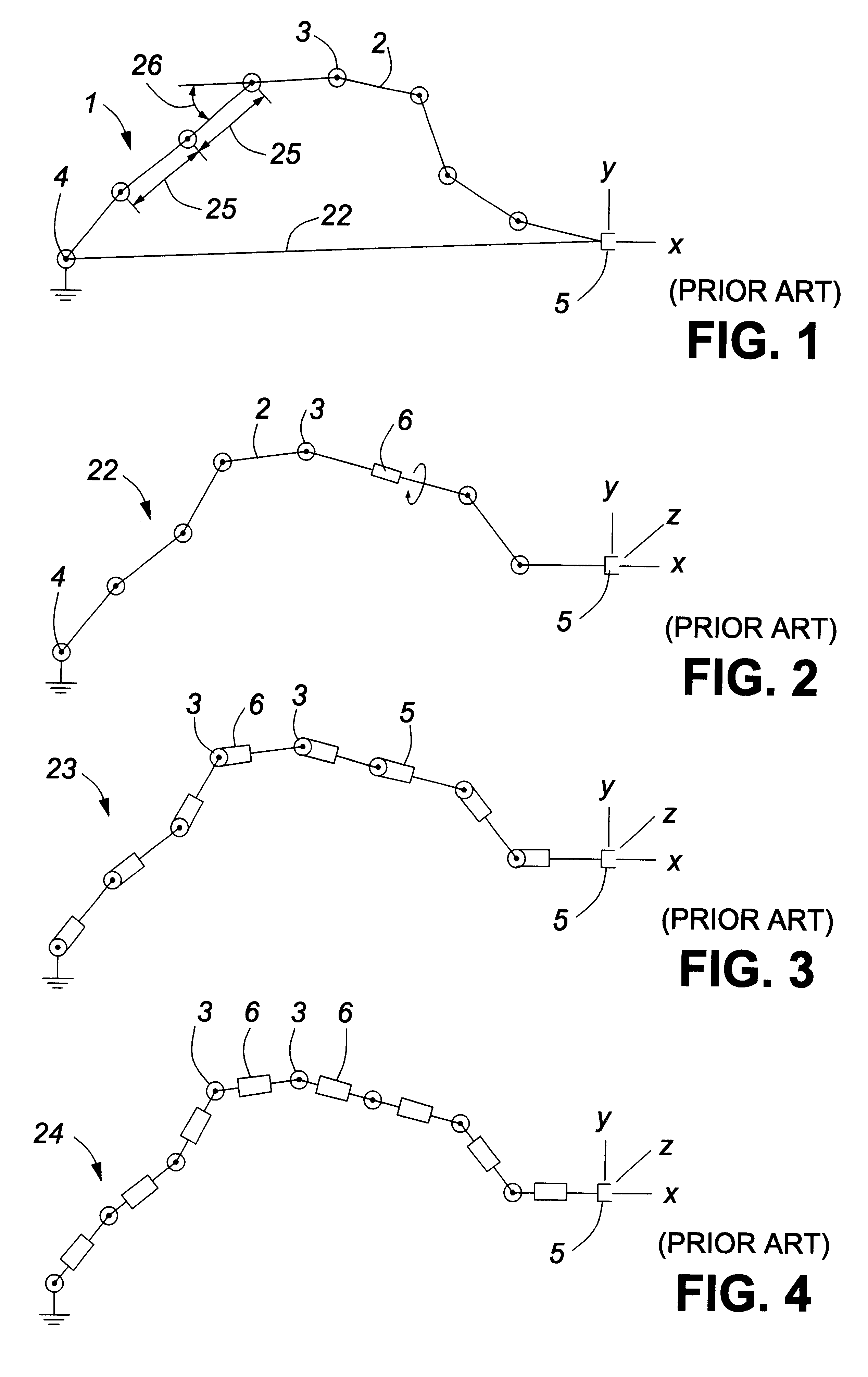
FIG. 1 represents a prior art mechanism 1 in the form of rigid links 2 that are coupled at joints 3 that have parallel axes. This mechanism 1 is therefore free to move or bend in a single plane. It is anchored to a reference point 4 at one end and may have an end effector 5 at its other end. All of the joints 3 are instrumented to have sensors (not shown) which provide information as to the angular orientation of the joints 3.

It is possible by processing the signals from the sensors and knowing the lengths of each of the links 2 to determine by calculation the distance to and position of the end effector 5 in space with respect to the reference point 4. In fact, the positions of all joints 3, and locations therebetween on specific links 2, can be calculated by interpolation.

With rigid links and mechanical joints it has not been possible in the past to multiply such elements to a number which is large enough to provide a shape or position measuring tool which has a high capacity for ...


PUM


Abstract

A measuring device for providing data corresponding to a geometric configuration in space, in the form of a flexible, compliant, measurement member capable of bending in at least one degree of freedom and extending along a medial axis or plane. The member has spaced flexure sensors distributed at known locations on the member and separated by known sensor spacing intervals to provide flexure signals indicating the local state of flexure present at the locations. The member comprises a multiplicity of formed, i.e. shaped, fibers, these fibers including sensing fibers having sensing portions which provide the flexure sensors, the sensing portions of different fibers being located at differing distances along the member so as to be located at the sensor spacing intervals, the formed fibers being in mutually supporting relationship, as by continuous or repeated contact with each other. Such fibers may constitute most or all of the member.

Description

FIELD OF THE INVENTIONThis invention relates to sensor technology. In particular, the invention relates to a tool or device for measuring the geometric location and configurations of objects in space. The invention is suited to robotic applications and to monitoring or measuring human geometry and motion. This invention represents modifications and improvements in the inventions described in U.S. Pat. No. 6,127,672, issued Oct. 3, 2000 to Lee Danisch, and PCT Appln. No. PCT / CA98 / 00213, published as WO98 / 41815, which are both incorporated by reference.A preferred application, amongst others, is in the field of animation effected by motion capture of movements by the human body.BACKGROUND TO THE INVENTIONVarious technologies have been applied to measure the location, orientation and surface shapes of objects in space.In the field of robotics it is known to determine the location of a flexible member formed by a series of rigid, linked elements in space by measuring the angular degree ...

Claims


Application Information

Patent Timeline
IPC IPC(8): G01B11/16G01D5/26G01D5/353
CPCG01B11/18G01D5/35383G01D5/268D04B1/12D10B2401/20D10B2403/02431D07B1/145A61B1/009
Inventor DANISCH, LEE ALLENDANISCH, JONATHAN FREEMANLUTES, JORDAN PATRICK
Owner CANADIAN SPACE AGENCY
Why Eureka
Try Eureka