Standalone Interbody Implants
a technology of interbody implants and implants, which is applied in the field of fixation devices, can solve the problems of obstructing the anatomy of the plate profile, affecting and deteriorating of the intervertebral discs in the spinal column, etc., and achieves the effect of promoting the fusion of adjacent vertebra
- Summary
- Abstract
- Description
- Claims
- Application Information
AI Technical Summary
Benefits of technology
Problems solved by technology
Method used
Image
Examples
second embodiment
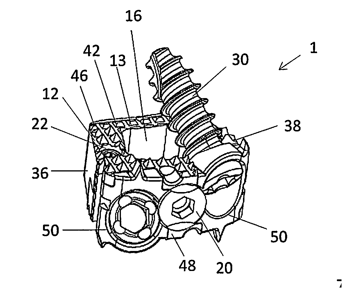
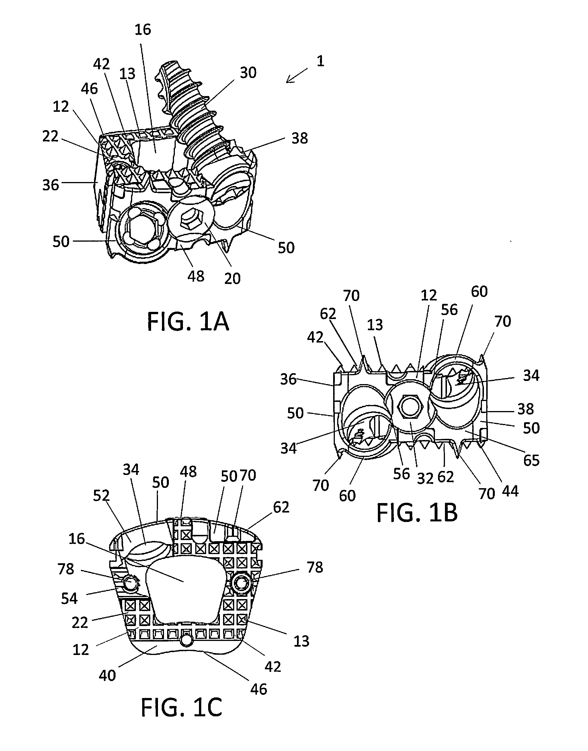
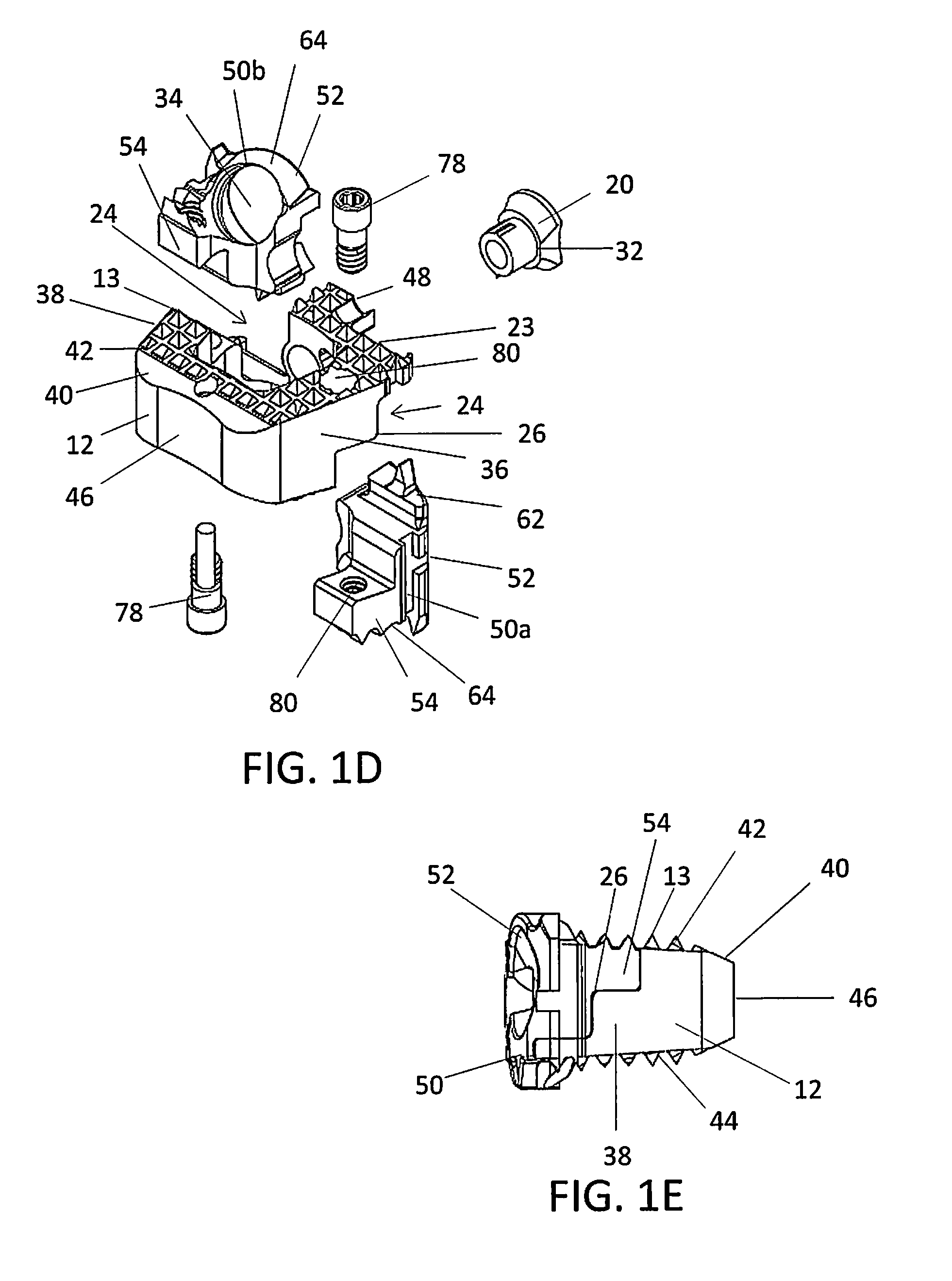
[0111]FIGS. 2A-2E show alternative views of an implant 10. In general, most of the structure of implant 10 is similar or comparable to the structure of implant 1. In this particular embodiment, the torsional stabilizers 70 on the upper surfaces 62 are replaced with a plurality of protrusions 13 or teeth. As shown in FIG. 2B, a portion of the upper surfaces 62 of the inserts 50a, 50b may include an extension with a plurality of protrusions 13 or teeth designed to extend the contact areas 22 of the superior and / or inferior surfaces 42, 44 of the spacer 12. The protrusions 13 on the upper surfaces 62 of the inserts 50a, 50b may complete a surface of the superior and inferior surfaces 42, 44 of the spacer 12 to enhance anchoring of the spacer 12. As shown in FIG. 2C, the spacer 12 may include the notch 23 in the cutout 24 in the superior and / or inferior surfaces 42, 44 of the spacer 12. The notch 23 may be uniform in shape and dimension or non-uniform. In particular, the notch 23 may ha...
third embodiment
[0112] FIGS. 3A-3E show alternative views an implant 100. In general, most of the structure of implant 100 is similar or comparable to the structure of implant 1. In this particular embodiment, different inserts 150 are provided. In particular, the upper surfaces 162 of the inserts 150a, 150b do not include a plurality of protrusions and are instead smooth. These smooth upper surfaces 162 do not complete the superior and inferior surfaces 142, 144 of the spacer 112. Instead, the smooth upper surfaces 162 are recessed and mated beneath the superior and inferior surfaces 142, 144 of the spacer 112. In addition, the cutouts 124 are modified from those shown in implant 1. For example, the superior and inferior surfaces 142, 144 of the spacer 112 are not notched to receive a portion of the insert 150, but instead extend to the proximal end 48 of the spacer. As is evident in FIG. 3B, a portion of the stepped projection 126 on the spacer 112 is extended to be contiguous and flush with the ...
fourth embodiment
[0113] FIGS. 4A-4E show an implant 200, which may be particularly suitable for an anterior lumbar procedure. In general, most of the structure of implant 200 is similar or comparable to the structure of implant 1. In this particular embodiment, three different inserts 250 provide the fastener apertures 234.
[0114]A shown in FIG. 4B, a first insert 250a is identical to a second insert 250b except as mirror images of one another to fit the respective cutouts 224 in the spacer 212. The first and second inserts 250a, 250b each define a fastener aperture 234. The first and second inserts 250a, 250b are each configured to allow a bone screw 230 to engage superior or inferior vertebra. Similar to implant 1, the spacer 212 may include one or more cutouts 224 sized and configured to retain the inserts 250. The cutouts 224 may further define a stepped projection 226 configured to mate with the arm 254 of the insert 250. The arm 254 may also be stepped and configured to mate with corresponding ...
PUM
 Abstract
Description
Claims
Application Information
 - R&D
- Intellectual Property
- Life Sciences
- Materials
- Tech Scout
- Unparalleled Data Quality
- Higher Quality Content
- 60% Fewer Hallucinations
Browse by: Latest US Patents, China's latest patents, Technical Efficacy Thesaurus, Application Domain, Technology Topic, Popular Technical Reports.
© 2025 PatSnap. All rights reserved.Legal|Privacy policy|Modern Slavery Act Transparency Statement|Sitemap|About US| Contact US: help@patsnap.com


