Cable interface for data and power supply

a power supply and data technology, applied in the field of cable interfaces for data and power supplies, can solve the problems of increased cost factor, increased cost, and increased cost of implementation, and achieve the effect of reducing the number of components, and reducing the cost of implementation

Inactive Publication Date: 2003-05-13
NOKIA NETWORKS OY
View PDF21 Cites 14 Cited by
  • Summary
  • Abstract
  • Description
  • Claims
  • Application Information

AI Technical Summary

Problems solved by technology

The problem is how in a divided radio link to transmit data and control in two directions, that is, in duplex form, and how to arrange the supply of electricity from one unit to another.
It is a drawback with the first method that an extra cable is needed, whereby corresponding cable adaptations are required.
The method of implementation is costly.
The drawback of the second method results from the circumstance that data is transmitted at an intermediate frequency in one direction.
This entails a need for extra components on the boards, which again is a cost increasing factor.
The drawback of the third method, as in the second method, is the need for extra components due to two different intermediate frequencies.

Method used


Image

  • Cable interface for data and power supply
  • Cable interface for data and power supply
  • Cable interface for data and power supply

Examples


Embodiment Construction

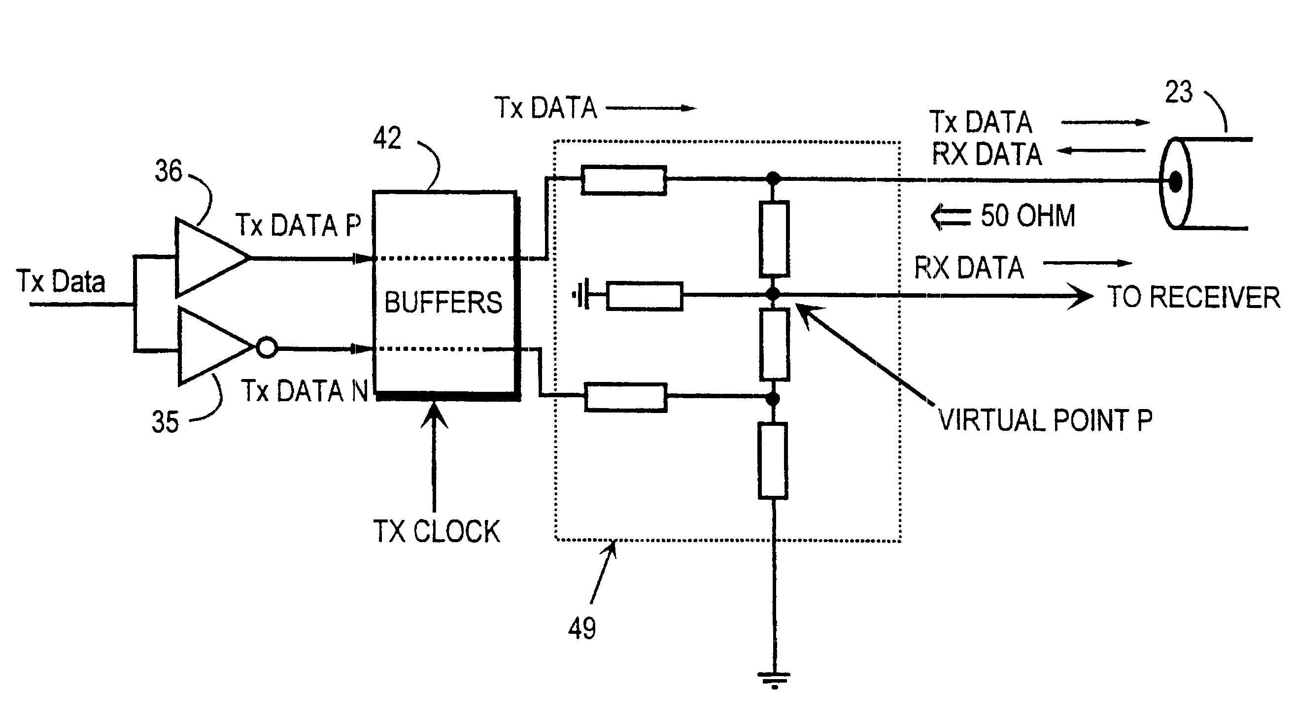
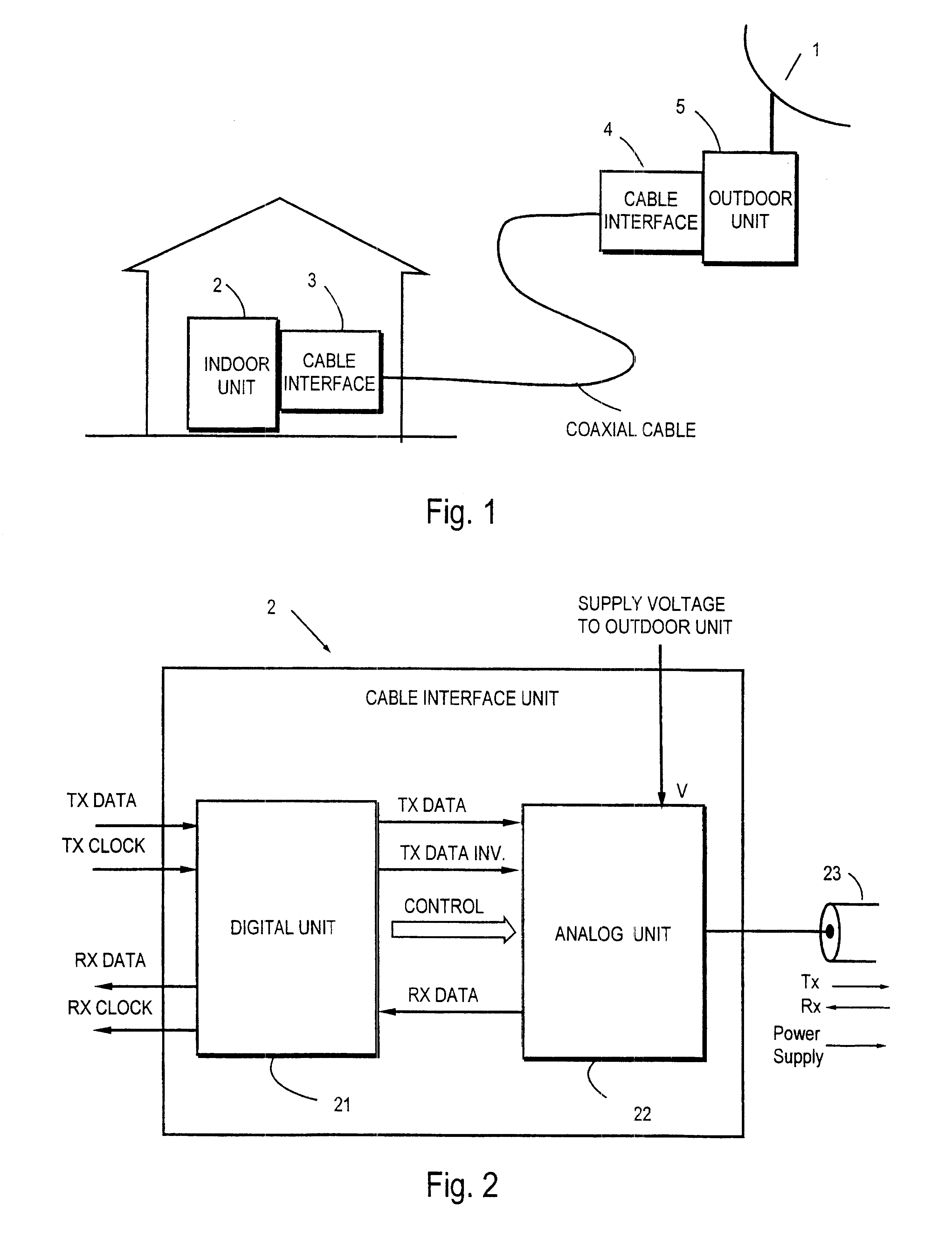
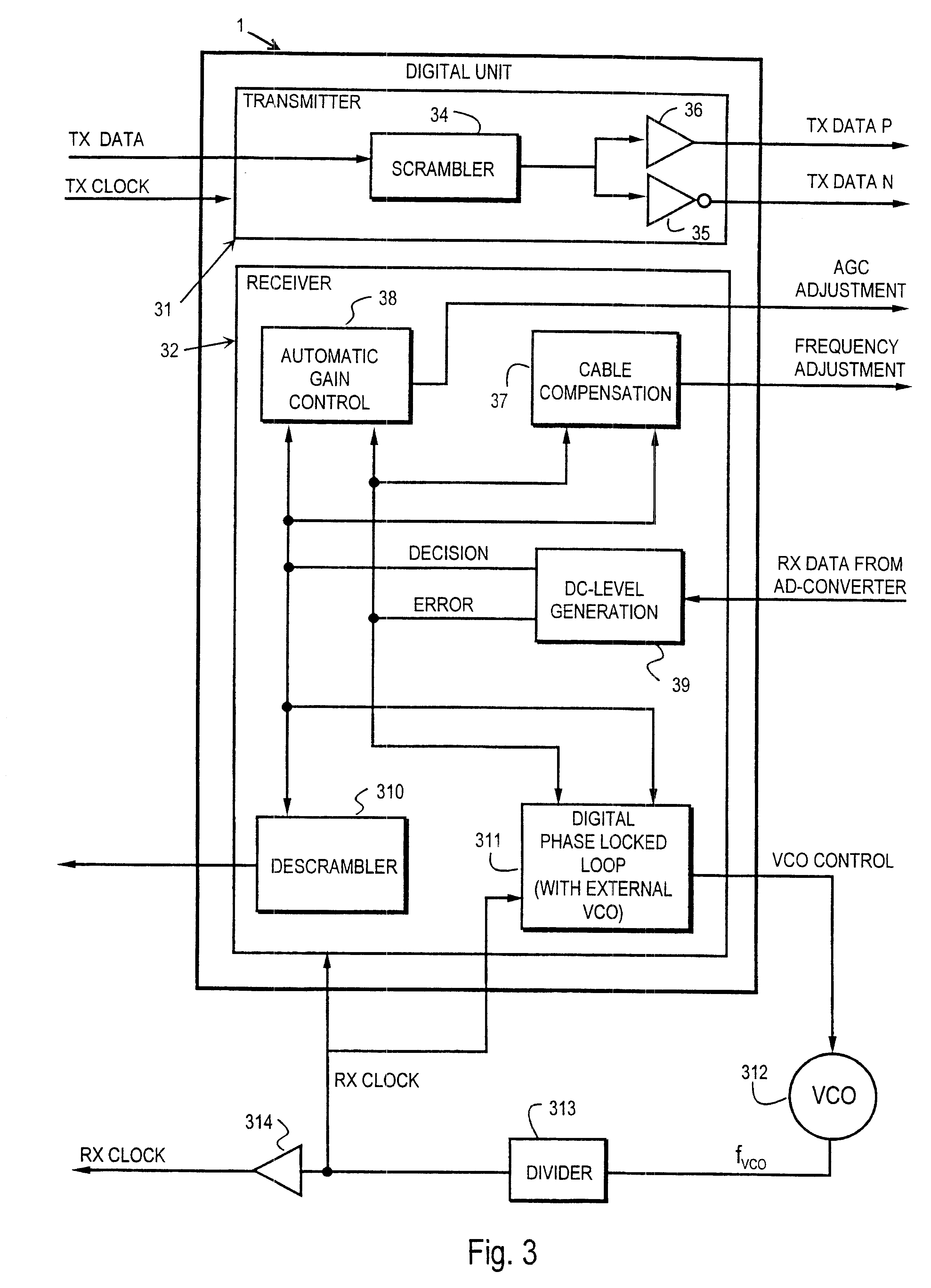
FIG. 2 is a rough presentation of the cable interface unit. The interface unit implements the CI (Cable Interface) between the cable and the telecommunication unit. The unit may be an indoor unit or an outdoor unit as shown in FIG. 1. The interface 2 is formed by two different blocks: the digital part 21, where all functions are digital, and the analog part 22, where correspondingly all functions are analog. All controls possibly needed by the analog part are formed in the digital part, from which they are transferred to the analog part. The interface contains arrangements, by which both data and a supply voltage can be transmitted to the same wire in one cable and, correspondingly, the data and supply voltage can be received from this same wire and separated from each other. The data may be useful data proper as well as control data. It is advantageous in many cases to implement the processing of the received data in a digital manner as far as possible, whereby the number of circui...


PUM


Abstract

The cable interface unit in accordance with the invention allows use of the same wire in one cable both for base-band transmission of data between telecommunication equipment in full duplex form and also for transmission of an operating voltage (V) from one device to another. In the transmission unit, data is transmitted through a hybrid connection (41) to a cable (23). After the hybrid connection, the operating voltage (V) is also brought to the cable with the aid of a diplexer (44). The hybrid connection separates the arriving data and conducts it to the receiver, where the data is shaped in an analog manner by correcting level distortions and thereupon in the digital signal processing a DECISION is made on what the received symbol is.

Description

This invention concerns a cable connection through which two pieces of telecommunication equipment can send data to each other and receive data from each other and through which one piece of equipment can provide the other piece of equipment with the operating voltage it needs. The invention especially concerns a connection for connecting a unit located close to an antenna in a divided radio link and a unit located farther away with a cable connecting the units.TECHNICAL BACKGROUNDFIG. 1 is a simplified view of the main parts of a divided radio link. The radio link may be e.g. a microwave link. The main parts include an indoor Unit 2 which is located in the internal space of an equipment cabinet or such and wherein processing of the received Rx signal is performed. The signal has been received by an Outdoor Unit 5 located physically close to an antenna 1. It has received a radio frequency signal from the antenna and after frequency conversion it has sent it further over the cable to...

Claims


Application Information

Patent Timeline
Patent Type & Authority Patents(United States)
IPC IPC(8): H04L5/14H04B3/54H04N7/10H04N7/173H04L12/10H04L25/02H04B3/04H04B3/02
CPCH04B3/03H04B3/04H04L5/1423H04N7/17309H04L25/02H04L25/10H04N7/10H04L12/10
Inventor MAKINEN, JARMOHAMALAINEN, VILLERAIMOVAARA, ANTTI
Owner NOKIA NETWORKS OY
Why Eureka
Try Eureka