Bar-shaped light guide, beam lighting device using the bar-shaped light guide, and surface lighting device using the beam lighting device

a beam lighting and bar-shaped technology, applied in lighting and heating equipment, instruments, machines/engines, etc., can solve the problems of increasing the number of assemble processes, reducing productivity, and increasing the cos

Inactive Publication Date: 2003-05-20
SANYO ELECTRIC CO LTD
View PDF5 Cites 111 Cited by
  • Summary
  • Abstract
  • Description
  • Claims
  • Application Information

AI Technical Summary

Problems solved by technology

To use such the beam light source as a light source for a light guide plate, for example, a diffusing sheet 261 and a lens sheet 262 should be arranged on the side of the light-emitting surface 213 for correcting light, resulting in degraded productivity caused by an increase in cost and the number of assemble processes.

Method used


Image

  • Bar-shaped light guide, beam lighting device using the bar-shaped light guide, and surface lighting device using the beam lighting device
  • Bar-shaped light guide, beam lighting device using the bar-shaped light guide, and surface lighting device using the beam lighting device
  • Bar-shaped light guide, beam lighting device using the bar-shaped light guide, and surface lighting device using the beam lighting device

Examples


first embodiment

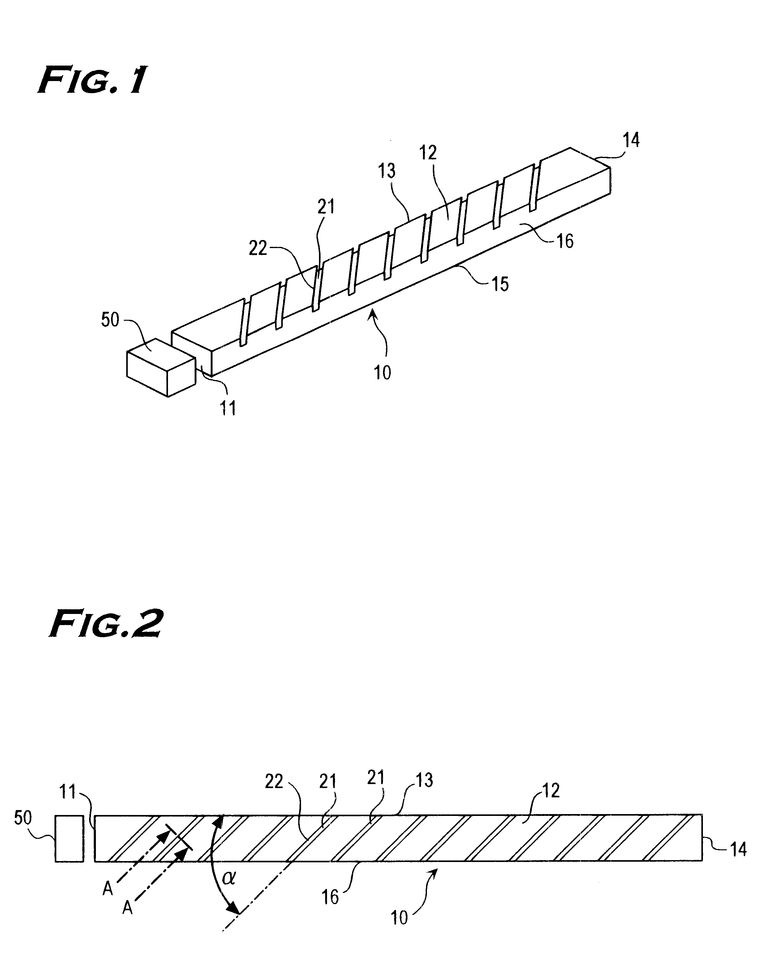
Explanation on this invention is made by referring to FIGS. 1-4. FIG. 1 is a perspective view illustrating an arrangement of a bar-shaped light guide and a light source. FIG. 2 is a top view illustrating the arrangement of the bar-shaped light guide and the light source.

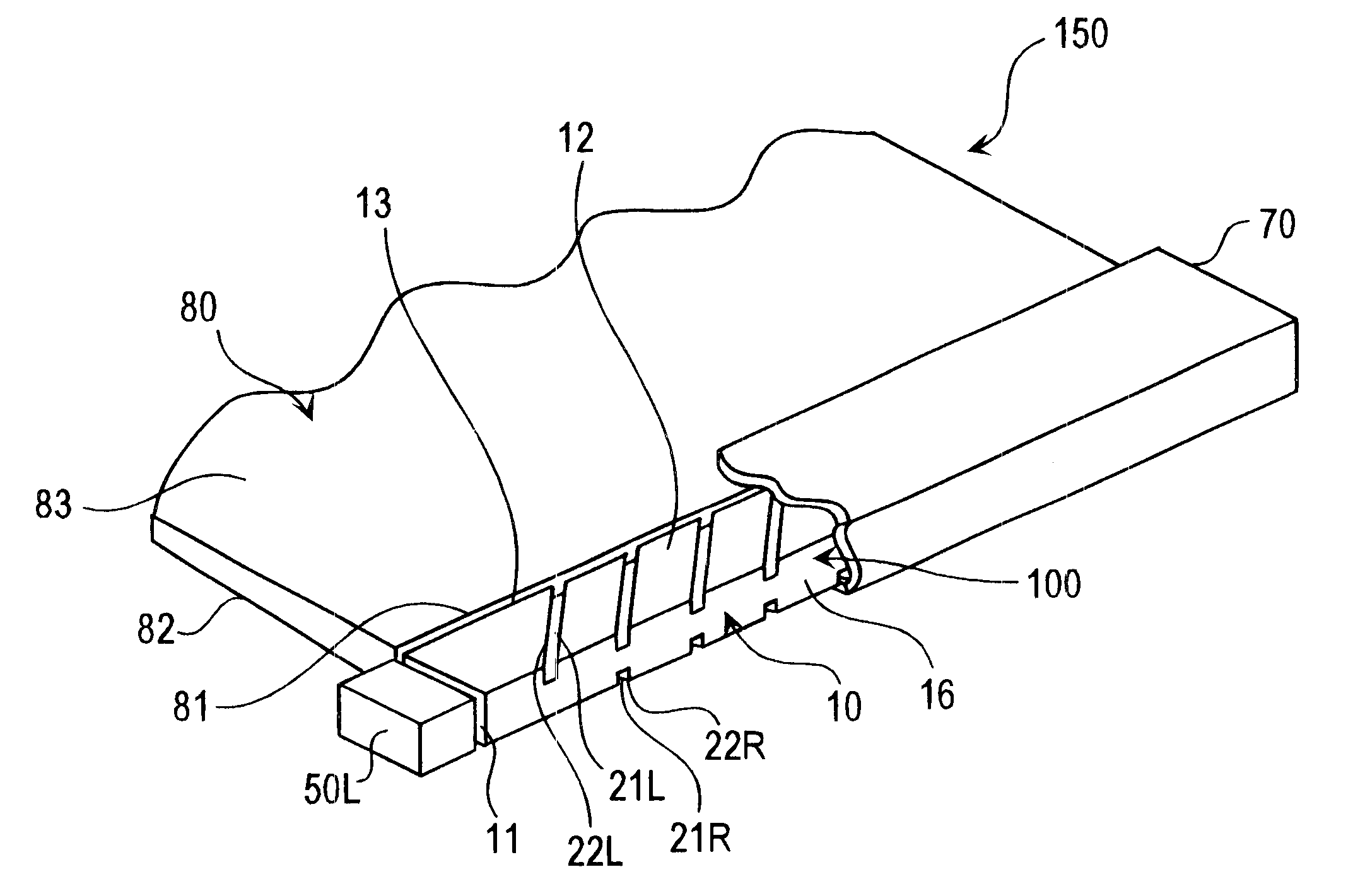
The bar-shaped light guide 10 has a right prism shape having following six faces; a light incident surface 11, a pattern surface 12, a light-emitting surface 13, an opposite surface 14 to the light incident surface 11, an opposite surface 15 to the pattern surface 12, and an opposite surface 16 to the light-emitting surface 13. The bar-shaped light guide 10, for example, is 60.1 mm in length, 2.8 mm in width (a length between the surface 13 and the surface 16), and 1 mm in height (a length between the surface 12 and the surface 15).

A distance between the pattern surface 12 and the opposite surface 15 to the pattern surface 12 (i.e. the height of the bar-shaped light guide) is shorter than a width of the pattern surfa...

second embodiment

Explanation of this invention is made by referring to FIGS. 5-6.

FIG. 5 is a top view illustrating a structure of a bar-shaped light guide including grooves formed on both surfaces and point light sources arranged on end surface on both sides of the bar-shaped light guide.

FIG. 6 is a perspective view illustrating the bar-shaped light guide having grooves formed on both surfaces according to the second embodiment of the present invention.

The bar-shaped light guide 10 has six surfaces; a first end surface 17 functioning as a first light incident surface, a first pattern surface 12, a light emitting surface 13, a second end surface 18 functioning as a second light incident surface and opposite to the first end surface 17, a second pattern surface 19 opposite to the first pattern surface 12, and a surface 16 opposite to the light emitting surface 13.

A first point light source 50L is arranged in a periphery of the first end surface 17 on one side of the bar-shaped light guide 10. A second...

third embodiment

Explanation on this invention is made by referring to FIG. 7.

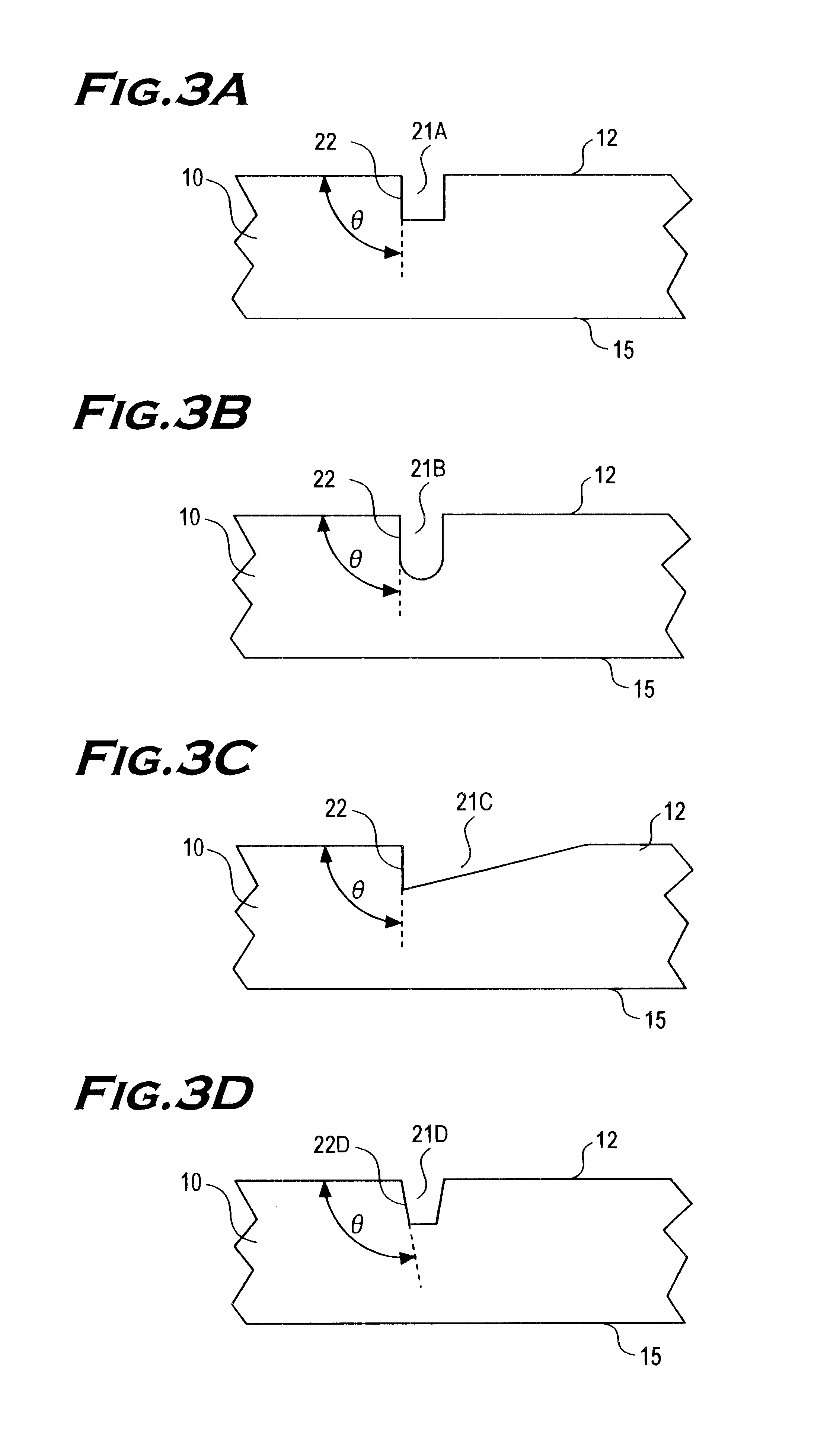
FIG. 7 illustrates a structure of the bar-shaped light guide shown in FIG. 5 for the second embodiment with V-shaped grooves formed on a surface opposite to a light emitting surface.

A plurality of V-shaped grooves 25 are formed on the surface opposite to the light emitting surface 13 of the bar-shaped light guide 10 along a longitudinal direction of the bar-shaped light guide 10. A V-shape of the groove is preferably formed by two sides forming a right angle of an isosceles triangle. The V-shaped groove 25 includes an inclining surface 25L on the first light source side and an inclining surface 25R on the second light source side. The inclining surface 25L on the first light source side reflects light emitted from the first point light source 50L to the light emitting light surface 13. The inclining surface 25R on the second light source side reflects light emitted from the second point light source 50R to the light emitti...


PUM


Abstract

This invention was made to reduce cost and the number of assembly processes and improve productivity by making viewing angle characteristics of light emitted from a light emitting surface even irrespective of a point in a bar-shaped light guide. A bar-shaped light guide of this invention comprises a light incident surface for receiving light emitted from a point light source, a light emitting surface, which is orthogonal to the light incident surface, for emitting light received on the light incident surface in a form of beam light, and a pattern surface made up of a side of the light incident surface and a side of the light emitting surface and having a plurality of grooves formed thereon. The plurality of grooves are regularly arranged on the pattern surface. An angle formed by the groove 106 and the side of the light emitting surface on a side of the point light source is 35-55°.

Description

1. Field of the InventionThis invention relates to a bar-shaped light guide for converting light from a point light source into beam light, a beam lighting device using the bar-shaped light guide, and a surface lighting device using the beam lighting device.2. Description of Prior ArtA beam lighting device, as shown in FIG. 16, for converting light emitted from a point light source such as a light emitting diode (LED) into beam light by a light guide is known. This beam lighting device includes point light sources 250, 250 on both end surfaces 211, 211 of a bar-shaped light guide 210, and a plurality of V-shaped grooves 225 are formed along a longitudinal direction of the bar-shaped light guide 210 on a reflecting surface 216 opposite to a light emitting surface 213. The light emitting surface 213 is a side surface of the light guide 210 in a longitudinal direction. The bar-shaped light guide 210 is a right prism comprising the light emitting surface 213, the reflecting surface 216,...

Claims


Application Information

Patent Timeline
Patent Type & Authority Patents(United States)
IPC IPC(8): F21V8/00
CPCG02B6/0038G02B6/0061
Inventor MABUCHI, KOJIGOTO, YOUICHIRONOSE, TORUIWATSUKI, NOBUO
Owner SANYO ELECTRIC CO LTD
Why Eureka
Try Eureka