
Method and apparatus for conveying fluids, particularly useful with respect to oil wells

Inactive Publication Date: 2003-05-27
PARADIGM GEOPHYSICAL LTD +4
View PDF8 Cites 27 Cited by
  • Summary
  • Abstract
  • Description
  • Claims
  • Application Information

AI Technical Summary

Benefits of technology

An important object of the present invention is to enhance the delivery of oil through an oil well in order to increase the production and / or reduce the production cost of the oil well, and / or to delay the point where an artificial lift becomes necessary.
The invention could also be applied wherein the fluid is a viscous liquid, the high velocity flow produced in the small cross-sectional area zones being effective to produce high shear stresses in the liquid, the turbulent flow in the abrupt transitions being effective to destroy the internal structure of the liquid, the pressure fluctuations produced in the liquid flowing through the alternating small cross-sectional area zones and large cross-sectional area zones being effective to produce viscosity reductions and liquid restructuring which further improve the hydrodynamic characteristics of the liquid.

Problems solved by technology

However, this natural pressure is continuously depleted during the operation of the oil well, so that an artificial lift is required if the oil well is to continue to produce.

Method used


Image

  • Method and apparatus for conveying fluids, particularly useful with respect to oil wells
  • Method and apparatus for conveying fluids, particularly useful with respect to oil wells
  • Method and apparatus for conveying fluids, particularly useful with respect to oil wells

Examples


Embodiment Construction

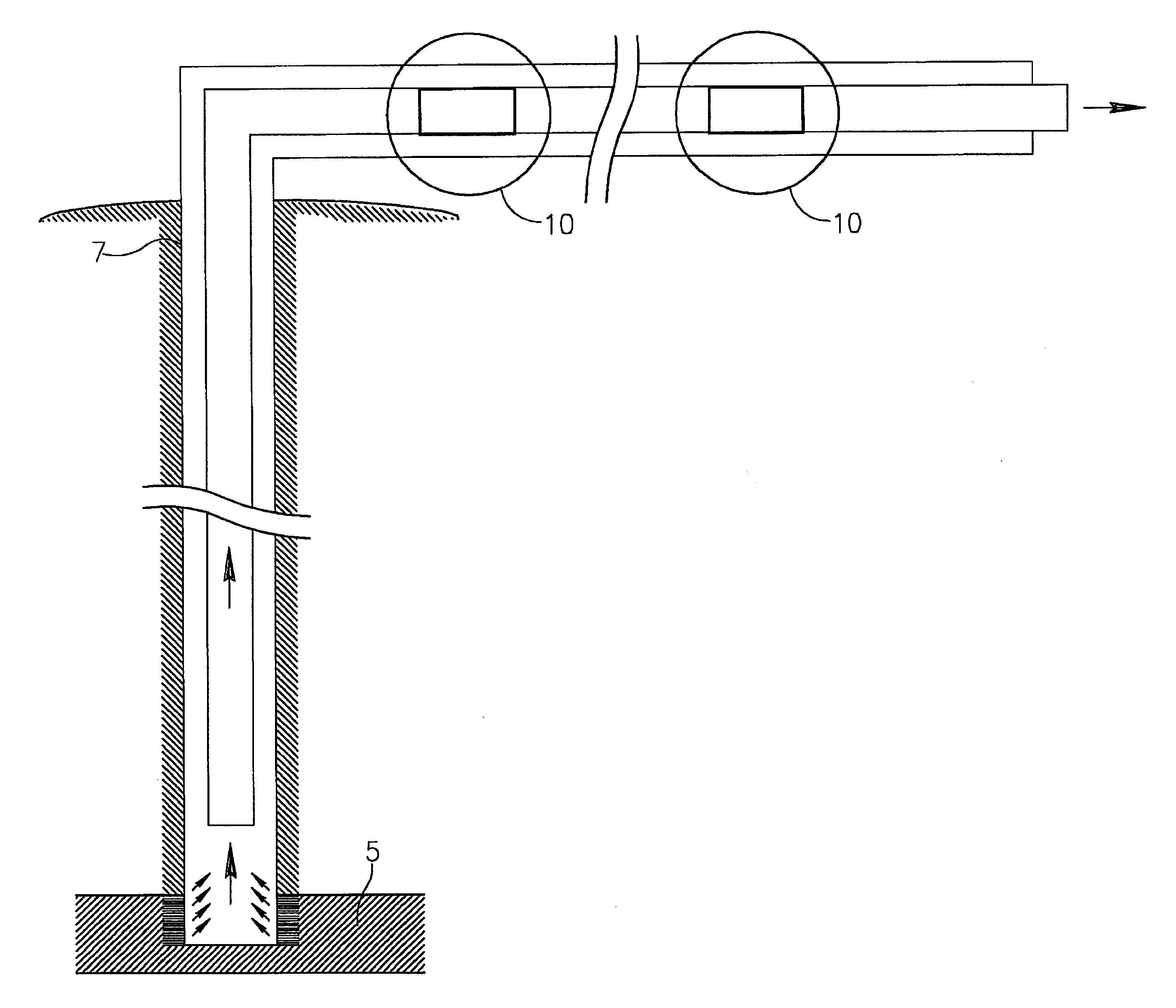
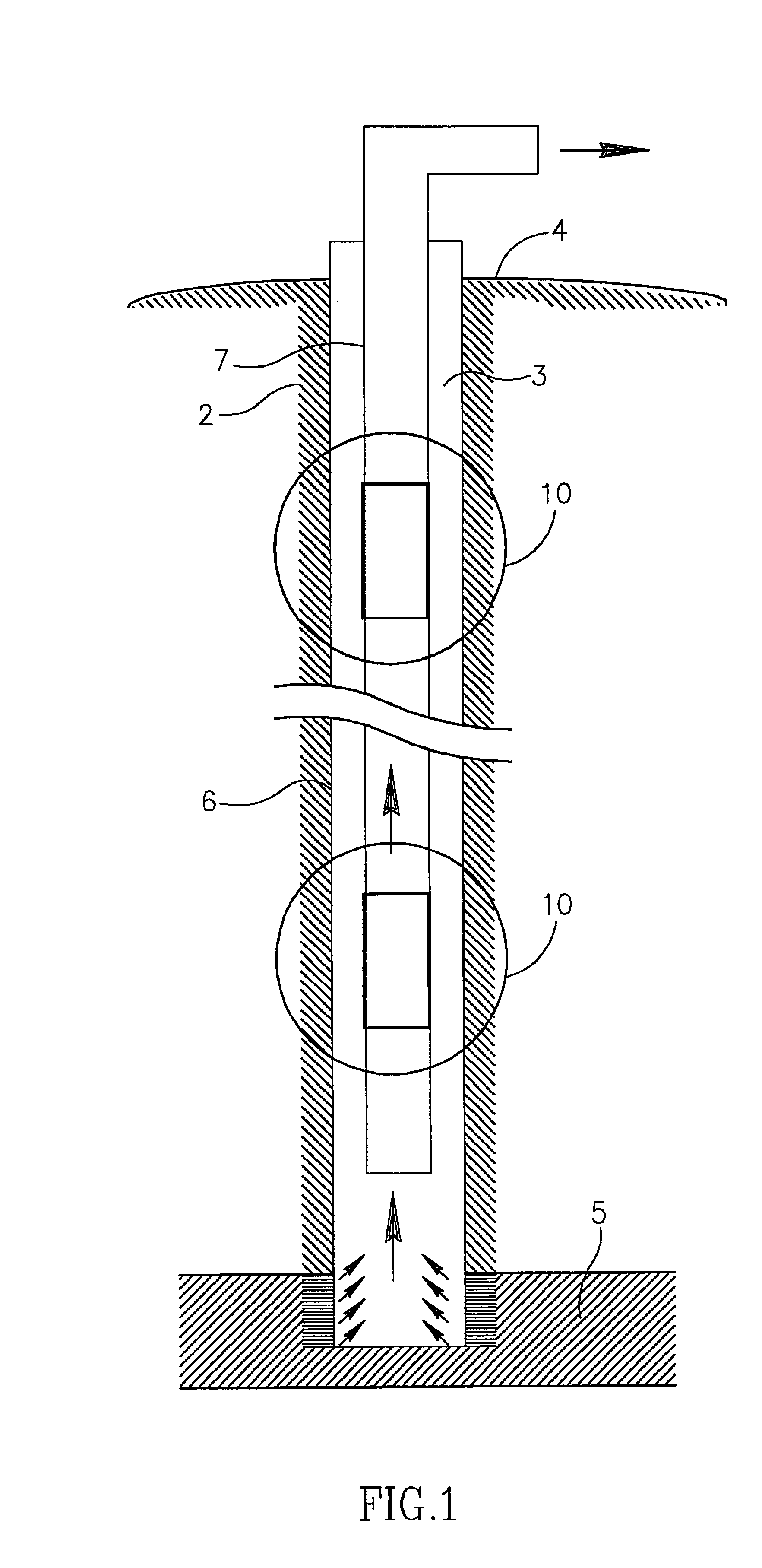
With reference first to FIG. 1, there is illustrated an oil well, generally designated 2, defined by a borehole 3 drilled through the earth from the surface 4 to an oil layer or reservoir 5 under the ground; a casing 6 sealing off the borehole; and 2 tubing 7 defining the flow passageway for the oil flowing from the reservoir 5 to the surface 4.

As known, such oil reservoirs 5 generally contain three fluids: oil, gas and salt water. Gas dissolved in the oil separates from the oil in the form of bubbles as the pressure is reduced below the bubble-point pressure. This process does not necessarily occur in the tubing, but may also take place in the reservoir itself, especially in the case of old reservoirs where the natural pressure is depleted. In such case, the oil-gas mixture enters the bottom-hole part of the well.

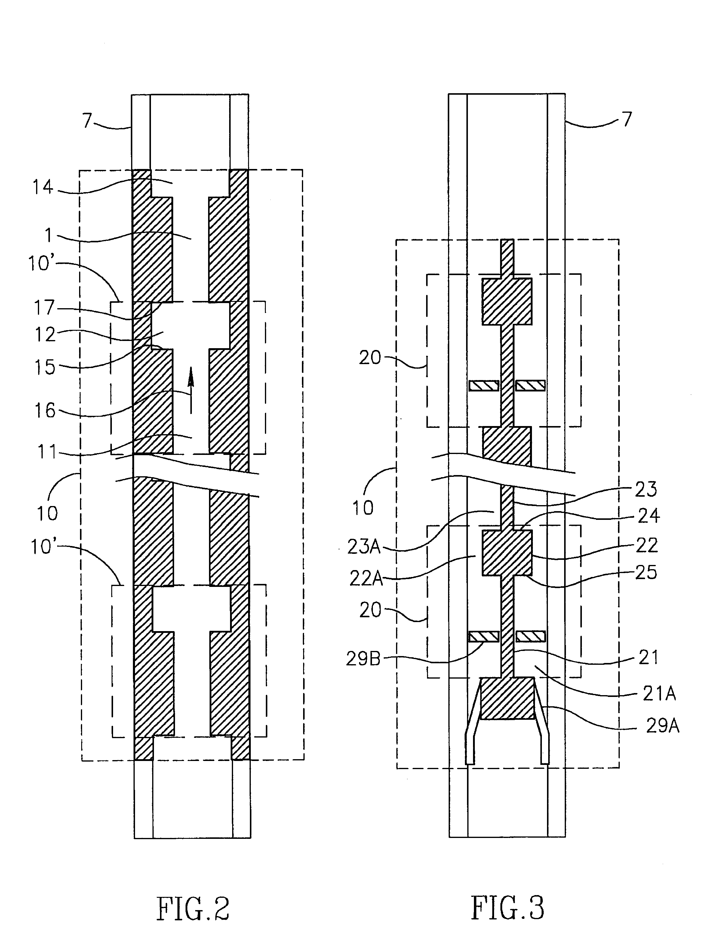
According to the present invention, the tubing 7 is provided with flow passageway zones of small cross-sectional areas alternating with zones of large cross-sectional area...


PUM


Abstract

A method and apparatus for conveying a fluid flowing through a flow passageway (16) in a tubing (7), by; introducing into the flow passageway (16) flow zones of small cross-sectional area (11) alternating with flow zones of large cross-sectional area (12) to produce high-velocity, low-pressure zones alternating with low-velocity, high-pressure zones; and providing abrupt transitions from the small cross-sectional area zones (11) to the large cross-sectional area zones (12) to produce a turbulent flow generating swirls and eddies (19) at such transitions. The method and apparatus are particulary useful in oil well applications where the fluid is an oil-gas mixture, but could be used in other applications where the fluid is a liquid-sand mixture, a gas-liquid mist, or a viscous liquid.

Description

FIELD AND BACKGROUND OF THE INVENTIONThe present invention relates to a method and apparatus for conveying fluids. The invention is particularly useful in conveying liquid-gas mixtures and is therefore described below with respect to these applications, but it will be appreciated that the invention could advantageously be used in many other applications, such as in conveying liquid-sand mixtures, gas-liquid mixtures, viscous liquids, and immiscible-liquid mixtures. Also, while the invention is particularly useful in oil production wells, it can also be used in gas and condensate production wells, liquid transporting systems, wells drilling systems, etc.Free-flowing oil wells utilize the natural energy of the underground reservoir, including the reservoir pressure and the energy of gas dissolved in the oil, for lifting the oil from the underground reservoir to the surface. However, this natural pressure is continuously depleted during the operation of the oil well, so that an artific...

Claims


Application Information

Patent Timeline
IPC IPC(8): E21B17/00F16L55/027F16L55/02E21B43/12
CPCE21B17/00F16L55/027E21B43/121E21B17/006
Inventor DVEYRIN, DMITRY
Owner PARADIGM GEOPHYSICAL LTD
Learn More