Interference suppression in a CDMA receiver
a receiver and interference technology, applied in the field of interference suppression in a cdma receiver, can solve the problems of multipath components that can interfere with one another, the resulting output of the rake detector, and the degradation of the orthogonality,
- Summary
- Abstract
- Description
- Claims
- Application Information
AI Technical Summary
Problems solved by technology
Method used
Image
Examples
Embodiment Construction
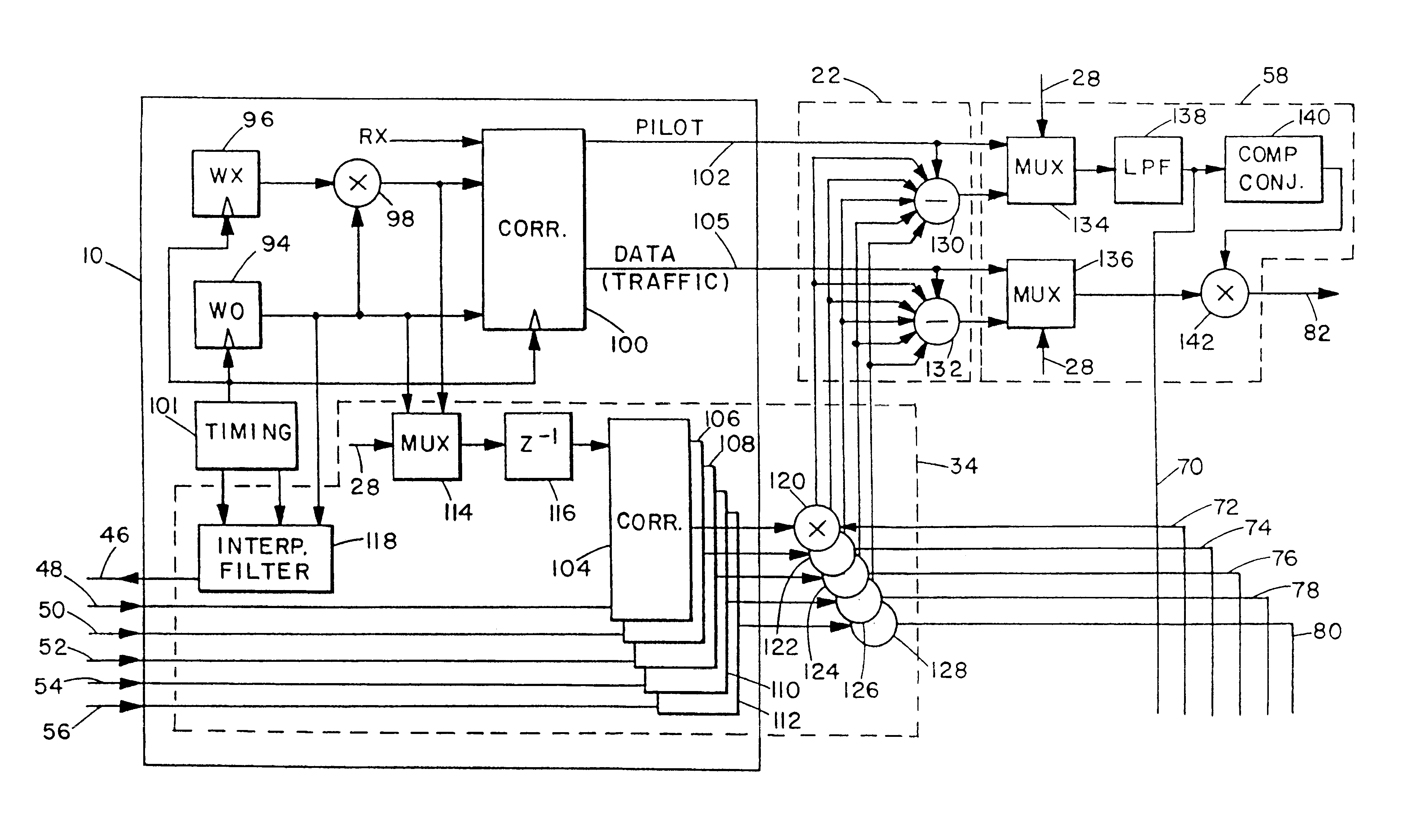
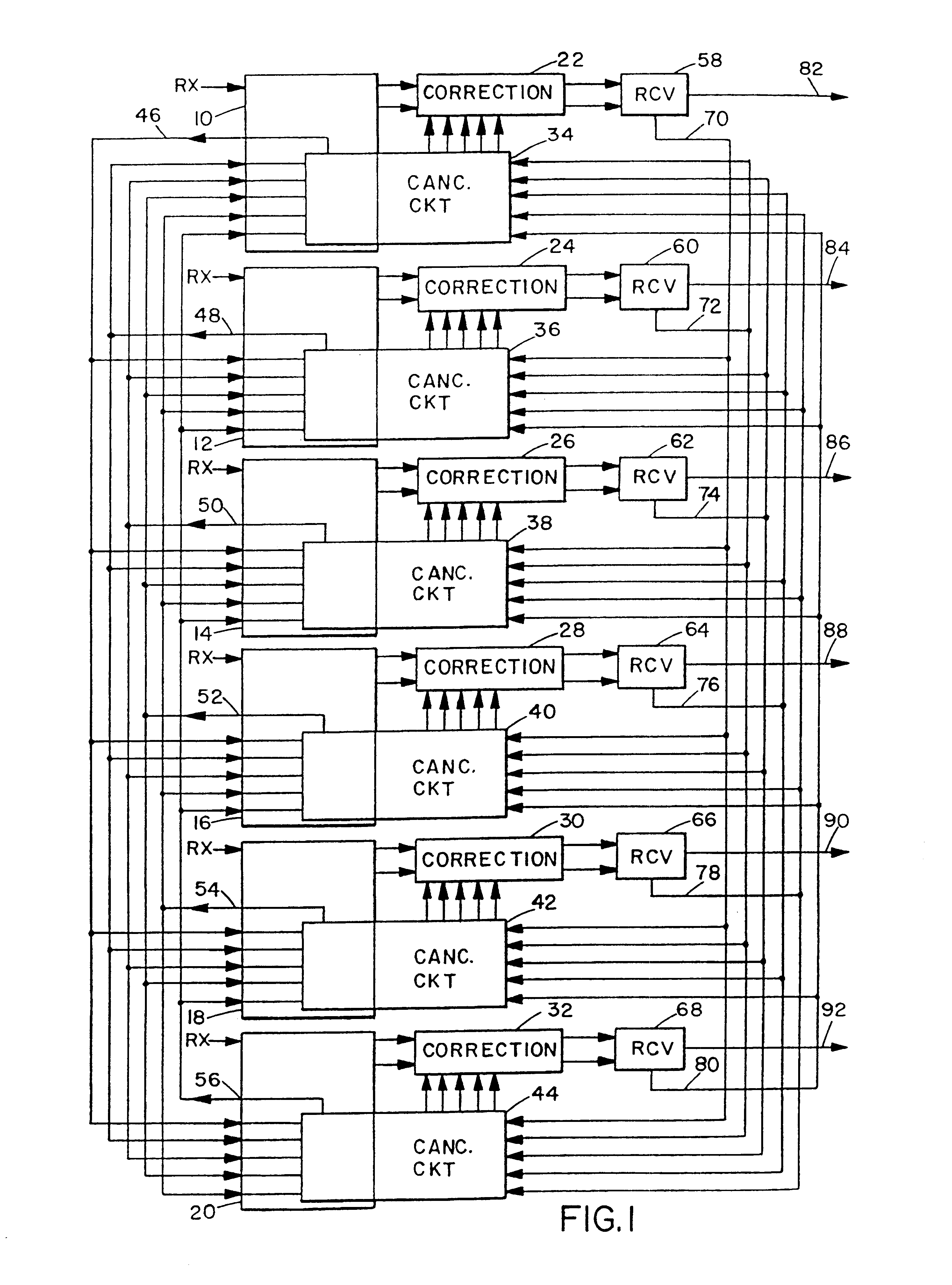
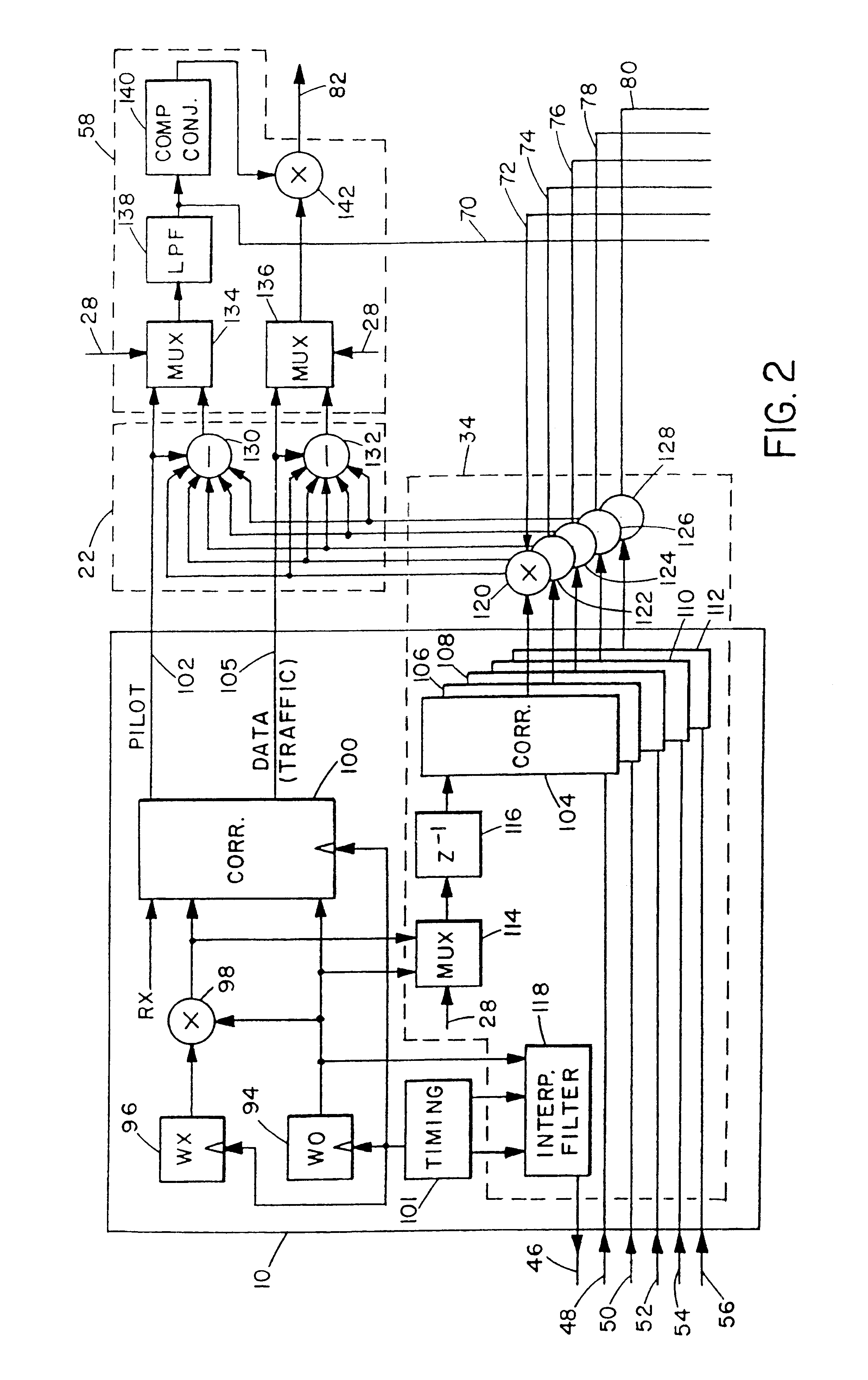
As illustrated in FIG. 1, a CDMA mobile telephone receiver has a six-finger Rake detector circuit (not shown in its entirety), including six corresponding finger circuits 10, 12, 14, 16, 18 and 20. Although the illustrated receiver uses six fingers, essentially any suitable number (n) of fingers could be used. The IS-95 CDMA standard describes the use of three fingers. As in a conventional CDMA receiver, each finger receives the complex baseband transmitted signal ("Rx") and demodulates or despreads one of the six strongest multipath signals into a pilot channel signal f1.sub.p (k) and a traffic (data) channel signal f1.sub.d (k). The traffic channel signal can be expressed as: ##EQU1##
where x'.sub.r (t) represents the received and filtered signal, z=(64k+i), the chip rate 1 / T.sub.s =1.2288*10.sup.6 s, c'(n) represents the pseudonoise (pn) code generated locally at the receiver, W.sub.n '(z) represents a Walsh code generated locally at the receiver, A.sub.1d (k) represents the desir...
PUM
 Abstract
Description
Claims
Application Information
 - R&D
- Intellectual Property
- Life Sciences
- Materials
- Tech Scout
- Unparalleled Data Quality
- Higher Quality Content
- 60% Fewer Hallucinations
Browse by: Latest US Patents, China's latest patents, Technical Efficacy Thesaurus, Application Domain, Technology Topic, Popular Technical Reports.
© 2025 PatSnap. All rights reserved.Legal|Privacy policy|Modern Slavery Act Transparency Statement|Sitemap|About US| Contact US: help@patsnap.com


