Rate of change detector for refrigerant floodback

Inactive Publication Date: 2003-06-17
CONCEPT TECH
View PDF8 Cites 124 Cited by
  • Summary
  • Abstract
  • Description
  • Claims
  • Application Information

AI Technical Summary

Benefits of technology

It is a primary object of the present invention to provide means for pro

Problems solved by technology

It does not disclose any provisio

Method used


Image

  • Rate of change detector for refrigerant floodback
  • Rate of change detector for refrigerant floodback
  • Rate of change detector for refrigerant floodback

Examples


Embodiment Construction

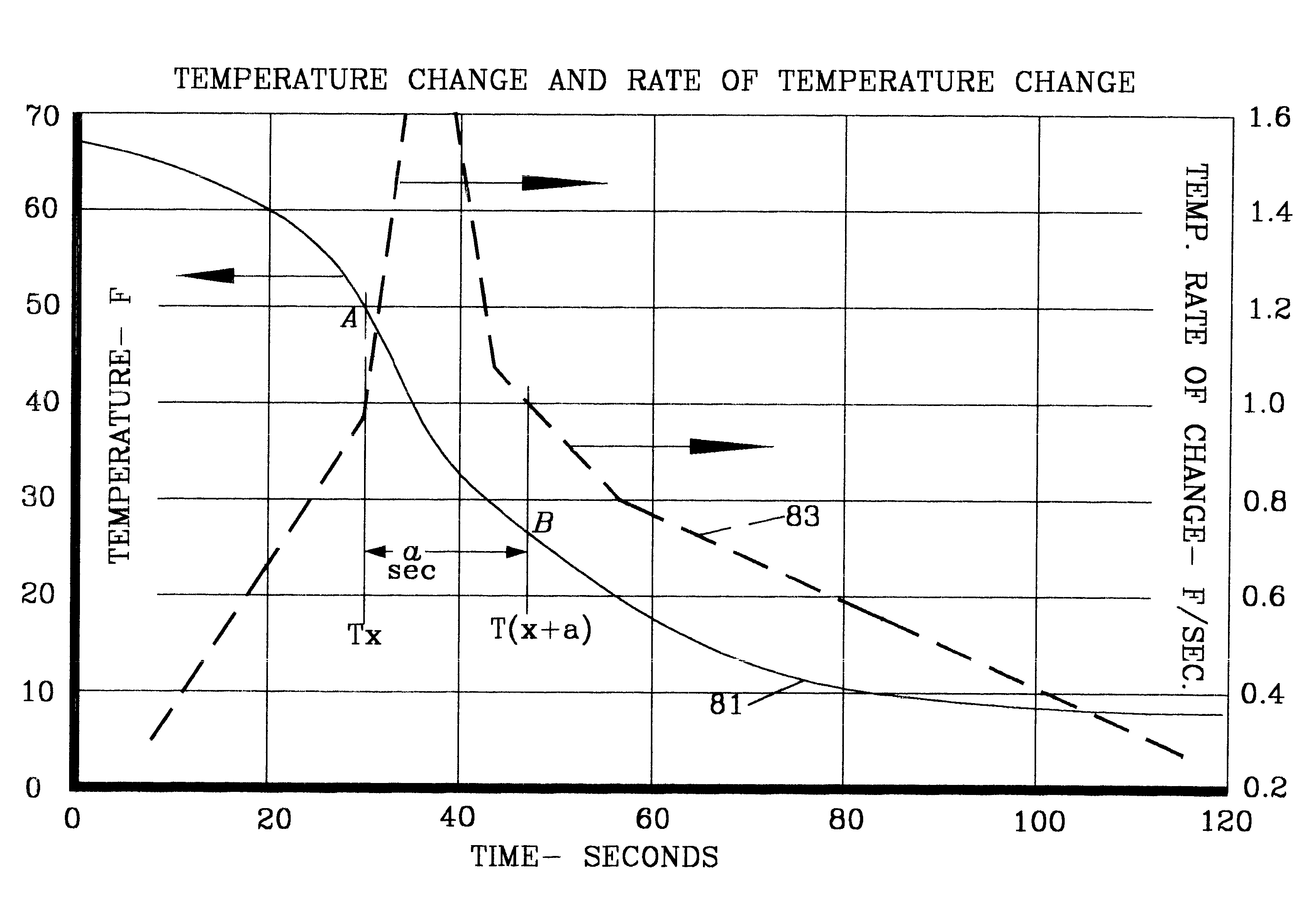
In FIG. 4 there is shown a graph having a horizontal time base abscissa in seconds, a left side ordinate in degrees Fahrenheit (F) temperature and a right side ordinate in degrees F temperature per second (F / Sec.), the units of rate-of-change. The unbroken line 81 is identified as temperature by a left pointing arrow. The heavier dashed line 83 is identified as cooling temperature rate-of-change by a right pointing arrow.

It should be noted that no representation is made that either the temperature nor the temperature rate-of-change lines can be precisely validated by comparison with any physical system since different types of systems and different types of construction and sensors and indicators produce different temperature and rate curves. However, all the curves, so far observed, have markedly similar shapes to which the principles of this invention apply.

Referring again to FIG. 4 there is plotted suction line temperature for a typical refrigerating system whose evaporator is op...


PUM


Abstract

A floodback detector for refrigerant systems employing any of: minimum suction temperature, temperature rate of change and duration thereof; minimum superheat, superheat rate of change and duration thereof.

Description

In refrigerating systems, a positive displacement compressor such as a piston type compressor is typically used to compress refrigerant gas from a lower suction pressure value to a much higher discharge pressure. Such compressors include a crankcase as a storage location for the lubricating oil. A suction conduit connects an evaporator or cooling coil to the compressor inlet.Positive displacement type compressors can easily be damaged should liquid refrigerant rather than vapor refrigerant be drawn either into its crankcase or its compression chamber. The term floodback is employed to denote and describe the condition when liquid refrigerant flows through the suction conduit and enters the crankcase or cylinders of a compressor. "Slugging" is the term used to describe the condition when so much incompressible liquid refrigerant enters the compressor cylinders or other types of compression chambers that audible noise of chattering or hammering occurs. In larger compressors, instantan...

Claims


Application Information

Patent Timeline
IPC IPC(8): F25B49/00G05D23/19
CPCF25B49/005G05D23/1917F25B2500/28F25B2700/21151F25B2700/1933
Inventor BARBIER, WILLIAM J.
Owner CONCEPT TECH
Why Eureka
Try Eureka