Drive unit for centrifuge rotor of a centrifugal separator

a technology of centrifuge rotor and drive unit, which is applied in the direction of centrifuges, shafts, bearings, etc., can solve the problems of not being particularly efficient in releasing heat from the air stream to the separator walls

Inactive Publication Date: 2003-06-17
ALFA LAVAL AB
View PDF8 Cites 17 Cited by
  • Summary
  • Abstract
  • Description
  • Claims
  • Application Information

AI Technical Summary

Benefits of technology

This object is obtained by the drive unit initially defined, which is characterised by means, arranged to cool said oil mist by permitting transportation of a substantial part of said oil mist from an outlet of the bearing member through at least a passage extending in heat transferring contact with a surrounding space outside the casing to the lower space. By such an arrangement, an efficient heat release is obtained from the oil mist, which has flown through the bearing, i.e. the cooling of the oil is improved in comparison with the corresponding cooling of previously known centrifugal separators. Since the oil mist, upon presentations to the bearing has a relatively low temperature, an efficient bearing cooling may be obtained by a relatively small flow of the oil mist through the bearing.

Problems solved by technology

In the centrifugal separators now available, the heat release from the air stream to the separator walls is however not particularly efficient.

Method used


Image

  • Drive unit for centrifuge rotor of a centrifugal separator
  • Drive unit for centrifuge rotor of a centrifugal separator
  • Drive unit for centrifuge rotor of a centrifugal separator

Examples


Embodiment Construction

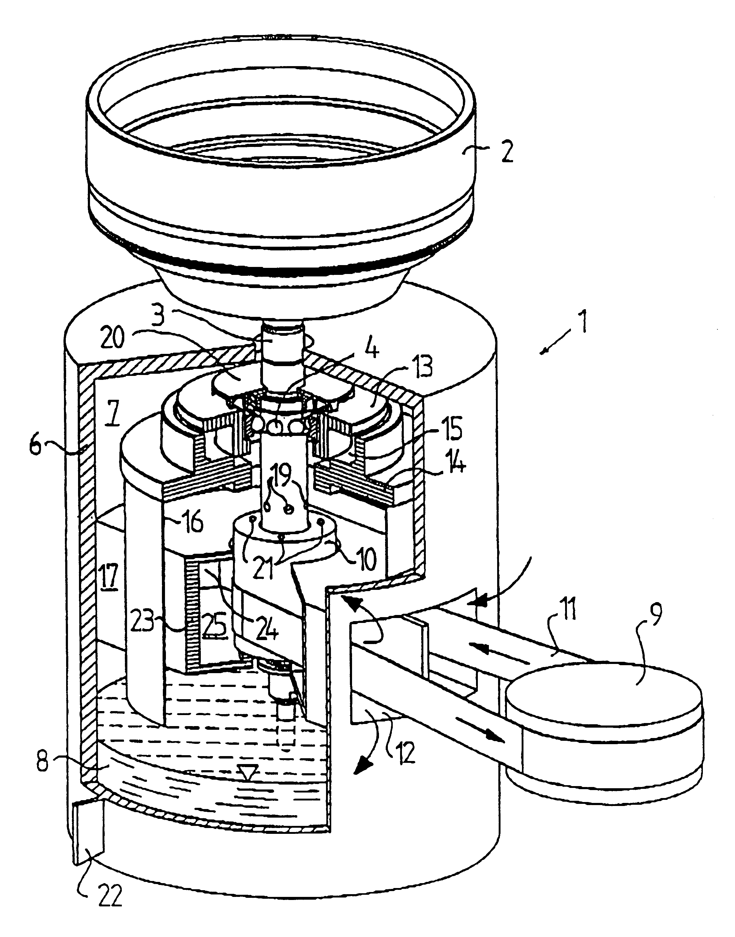
FIG. 1 discloses a drive unit 1 for a partly disclosed centrifuge rotor 2. The drive unit 1 and the centrifuge rotor 2 form together substantial components of a centrifugal separator.

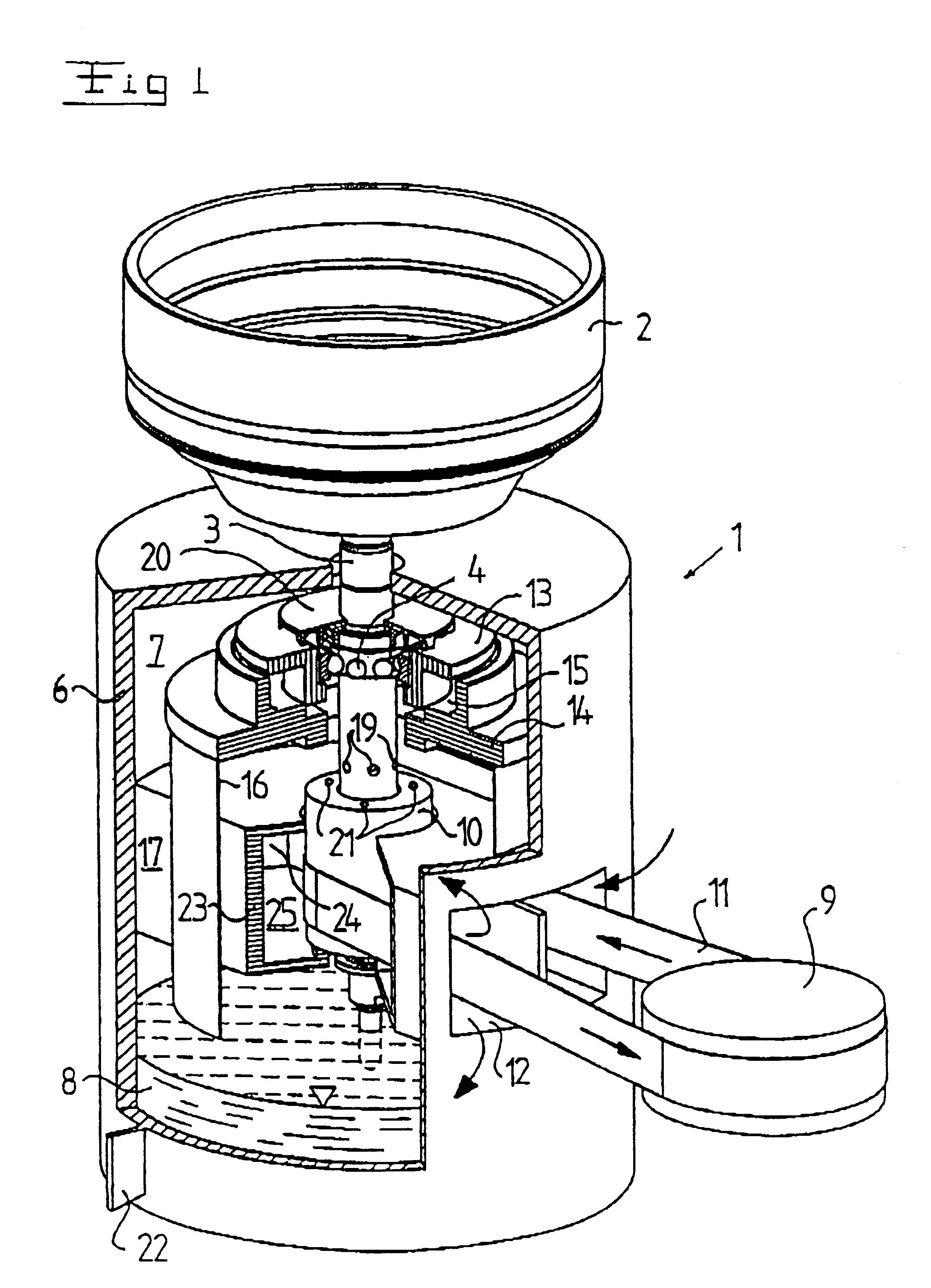
The drive unit 1 includes a drive shaft 3, which supports the centrifuge rotor 2 and is rotatable around a rotary axis z and carried by means of a first, upper bearing member 4 and a second, lower bearing member 5, see FIG. 2. Furthermore, the drive unit 1 includes a casing 6, which delimits an inner space. The inner space consists of an upper space 7, in which the drive shaft 3, the first bearing member 4, and the second bearing member 5 are located, as well as a lower space 8, which is designed as an oil pan and arranged to store a quantity of liquid oil. The drive unit 1 also includes a drive motor (not disclosed) which is connected to a belt pulley 9. The drive motor and the belt pulley 9 are provided outside the casing 6 and connected to a belt pulley 10, which is fixedly provided on the drive shaf...


PUM

PropertyMeasurementUnit
vertical lengthaaaaaaaaaa
heataaaaaaaaaa
temperatureaaaaaaaaaa

Abstract

The invention refers to a drive unit (1) for a centrifuge rotor (2) of a centrifugal separator. The drive unit (1) includes a drive shaft (3), which is arranged to support said centrifuge rotor (2) and is rotatably journalled around an axis (z) of rotation, a casing (6), which forms an inner space for the drive shaft (3), and a drive motor shaft (9), which is provided outside the casing (6) and connected to the drive shaft (3) by means of a transferring member (11) which extends through a passage (12) in the casing (6). A shielding member (23) is provided inside the casing (6) in such a way that the part of the transferring member (11), which is located inside the casing (6) is shielded from the inner space, wherein the shielding member (23) forms a channel, which extends through the casing (6) and is shielded from the inner space of the casing.

Description

FIELD OF THE PRESENT INVENTIONThe present invention refers to a drive unit for a centrifuge rotor of a centrifugal separator, wherein the drive unit includes a drive shaft, which is arranged to carry said centrifuge rotor and is rotatably journalled in at least one bearing member, and a casing, which delimits an upper space, in which the drive shaft and said first bearing member are located, and a lower space for storing liquid oil, and wherein the drive unit includes first means, which are arranged to create a flow of air and said oil for forming an oil mist and to bring this oil mist to flow through said bearing member for cooling and lubricating thereof.BACKGROUND OF THE PRESENT INVENTIONThe cooling of bearings of known drive units for centrifugal separators frequently rely on an internal circulating air stream, to which are supplied droplets of oil from an oil pan in a lower space in the drive unit in such a way that an oil mist is formed. The air stream with the oil mist is cir...

Claims


Application Information

Patent Timeline
Patent Type & Authority Patents(United States)
IPC IPC(8): B04B9/12B04B9/00
CPCB04B9/12F16C33/6662F16C2320/42
Inventor KLINTENSTEDT, KJELLLARSEN, TORBJORNSETTERBERG, JANSZEPESSY, STEFAN
Owner ALFA LAVAL AB
Why Eureka
Try Eureka