Flat magnetic core

a magnetic core and flat technology, applied in the direction of magnetic cores/yokes, transformers/inductance magnetic cores, magnetic bodies, etc., can solve the problems of windings and production with the aid of expensive thin-film processes

Inactive Publication Date: 2003-06-17
VACUUMSCHMELZE GMBH & CO KG
View PDF27 Cites 20 Cited by
  • Summary
  • Abstract
  • Description
  • Claims
  • Application Information

AI Technical Summary

Problems solved by technology

A disadvantage of this type of component is that it can only be produced with the aid of a costly thin-film process.
A further disadvantage is that with this type of component, the windings must also be produced with the aid of a costly thin-film process.

Method used


Image

  • Flat magnetic core
  • Flat magnetic core
  • Flat magnetic core

Examples


Embodiment Construction

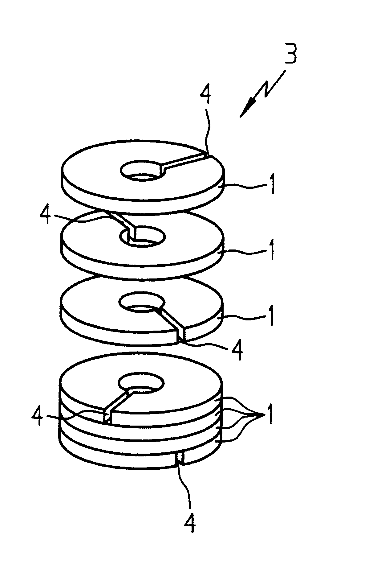
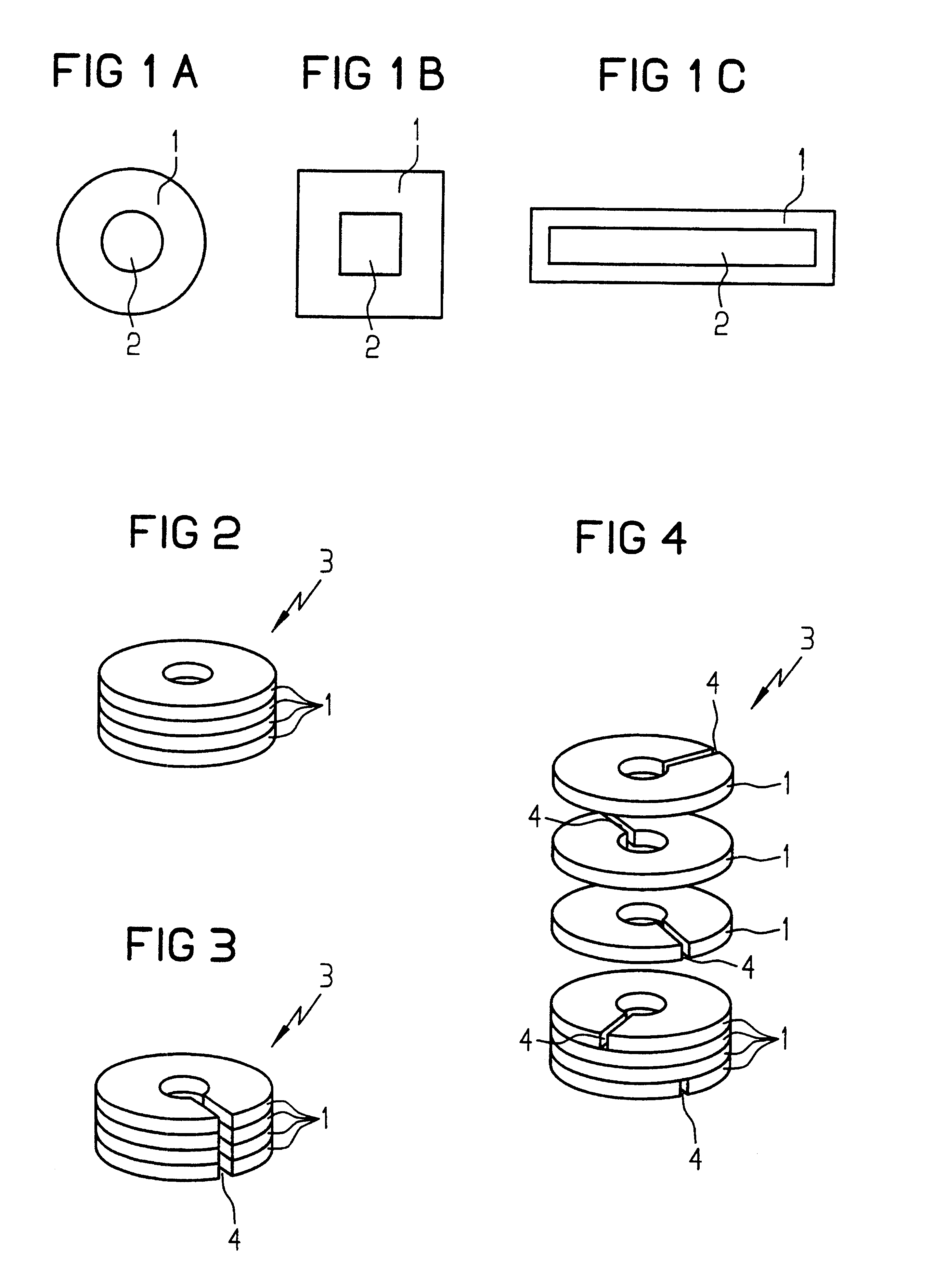
Various embodiments of a magnetic sheet 1 are illustrated in FIGS. 1A to 1C. The magnetic sheet 1 illustrated in FIG. 1A has a circular ring shape. In contrast, the magnetic sheets 1 from FIGS. 1B and 1C have a ring shape with rectangular contours. The magnetic sheets 1 are, for practical purposes, produced from an amorphous or nanocrystalline alloy. Amorphous alloys based on iron are, for example, known from U.S. Pat. No. 4,144,058. Amorphous alloys based on cobalt are, for example, known from EP-A-0 021 101. Finally, nanocrystalline alloys are described in EP-A-0 271 657. Thin sheets with a typical thickness of 10 to 25 .mu.m, or sometimes, greater or lesser thicknesses, can be produced from the materials mentioned. The ring-shaped magnetic sheets 1 can then be stamped out of the thin sheets.

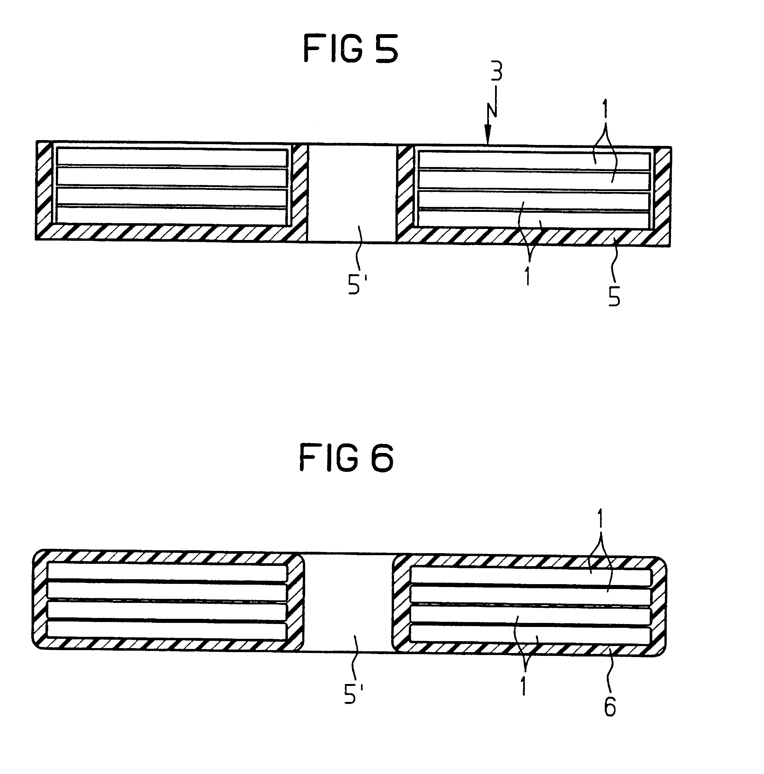
The stacked magnetic sheets 1 result in a toroidal core 3, as illustrated in FIG. 2, with the thickness of the magnetic sheets 1 being exaggerated in FIG. 2 in comparison to the diameter, as t...


PUM

PropertyMeasurementUnit
thicknessesaaaaaaaaaa
thicknessaaaaaaaaaa
frequenciesaaaaaaaaaa

Abstract

A toroidal tape core is produced from magnetic sheets (1) which may have slits (4). In order to improve the behavior of the toroidal cores (3) at high frequencies, the magnetic sheets (1) have a high surface roughness. The surface roughness of each magnetic sheet (1) is at least equal to the skin penetration depth at the frequency being used.

Description

1. Field of the InventionThe invention concerns a component of low overall height for circuit boards having a magnetic region formed by at least one layer made of a soft-magnetic material.2. Description of the Related ArtA component of this type is known from U.S. Pat. No. 5,529,831. The known component is produced by applying insulator films, conductor films, and a magnetic film onto the substrate. A typical sputtering process is used to apply these films.A disadvantage of this type of component is that it can only be produced with the aid of a costly thin-film process. In addition, depending on the process, only low film thicknesses in the range of a few .mu.m can be produced. The cross-sections of the magnetic regions produced with the aid of this process are correspondingly small. A further disadvantage is that with this type of component, the windings must also be produced with the aid of a costly thin-film process.Proceeding from this prior art, the object of the invention is ...

Claims


Application Information

Patent Timeline
Patent Type & Authority Patents(United States)
IPC IPC(8): H01F41/02H01F17/04H01F3/02H01F17/00H01F3/00
CPCH01F41/0226H01F17/04H01F3/02H01F17/0013H01F1/15333
Inventor HUNDT, HARALDBEICHLER, JOHANNES
Owner VACUUMSCHMELZE GMBH & CO KG
Why Eureka
Try Eureka