Light guide plate, surface light source device of side light type and liquid crystal display

a surface light source and liquid crystal display technology, applied in static indicating devices, lighting and heating apparatuses, instruments, etc., can solve the problems of increased number of components or complicated structure, increased number of components, and reflection appearance, so as to prevent abnormal emission and avoid display quality from falling.

Inactive Publication Date: 2003-07-01
ENPLAS CORP
View PDF8 Cites 42 Cited by
  • Summary
  • Abstract
  • Description
  • Claims
  • Application Information

AI Technical Summary

Benefits of technology

An object of the present invention is to provide a light guide plate which is improved so that the above- described problems are solved. Another object of the present invention is to provide a surface light source device of side light type which is able to suppress abnormal emission by means of the improved light guide plate. A still another object of the present invention is to provide a liquid crystal display which is able to avoid display quality from falling by employing the surface light source device of side light type.

Problems solved by technology

Such directivity correction can be achieved by an alternative such as an additional prism sheet arrangement, which leads to increased number of components or more complicated structure.
However, this method is subject to another problem called "reflective appearance".
In usual cases, such phenomena bring several excessively bright regions like bright lines.
Such abnormal emission deteriorates illumination quality of a surface light source device of side light type.
And besides, if the surface light source device is applied to a liquid crystal display, display quality will be reduced.

Method used


Image

  • Light guide plate, surface light source device of side light type and liquid crystal display
  • Light guide plate, surface light source device of side light type and liquid crystal display
  • Light guide plate, surface light source device of side light type and liquid crystal display

Examples


first embodiment

(1) First Embodiment

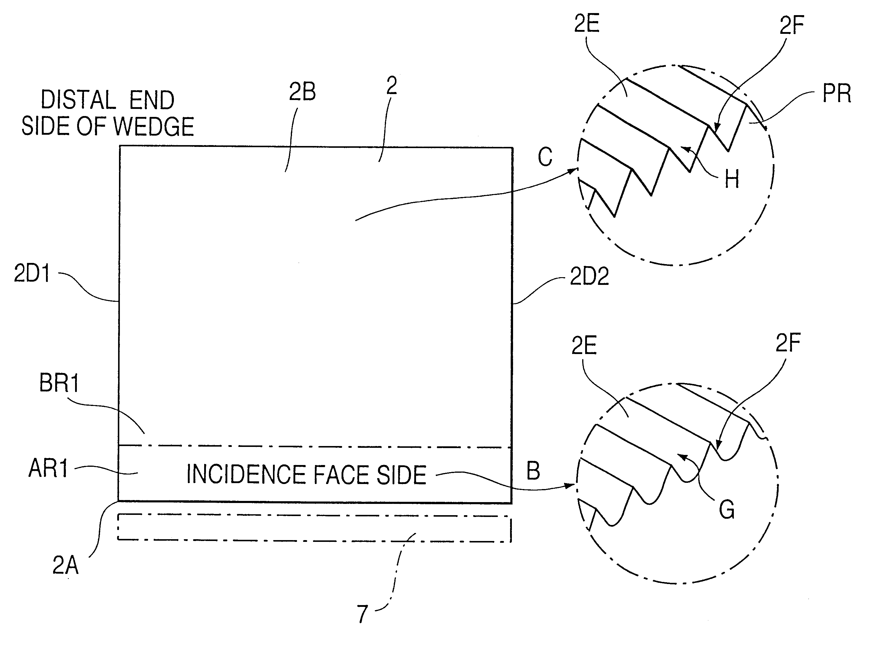
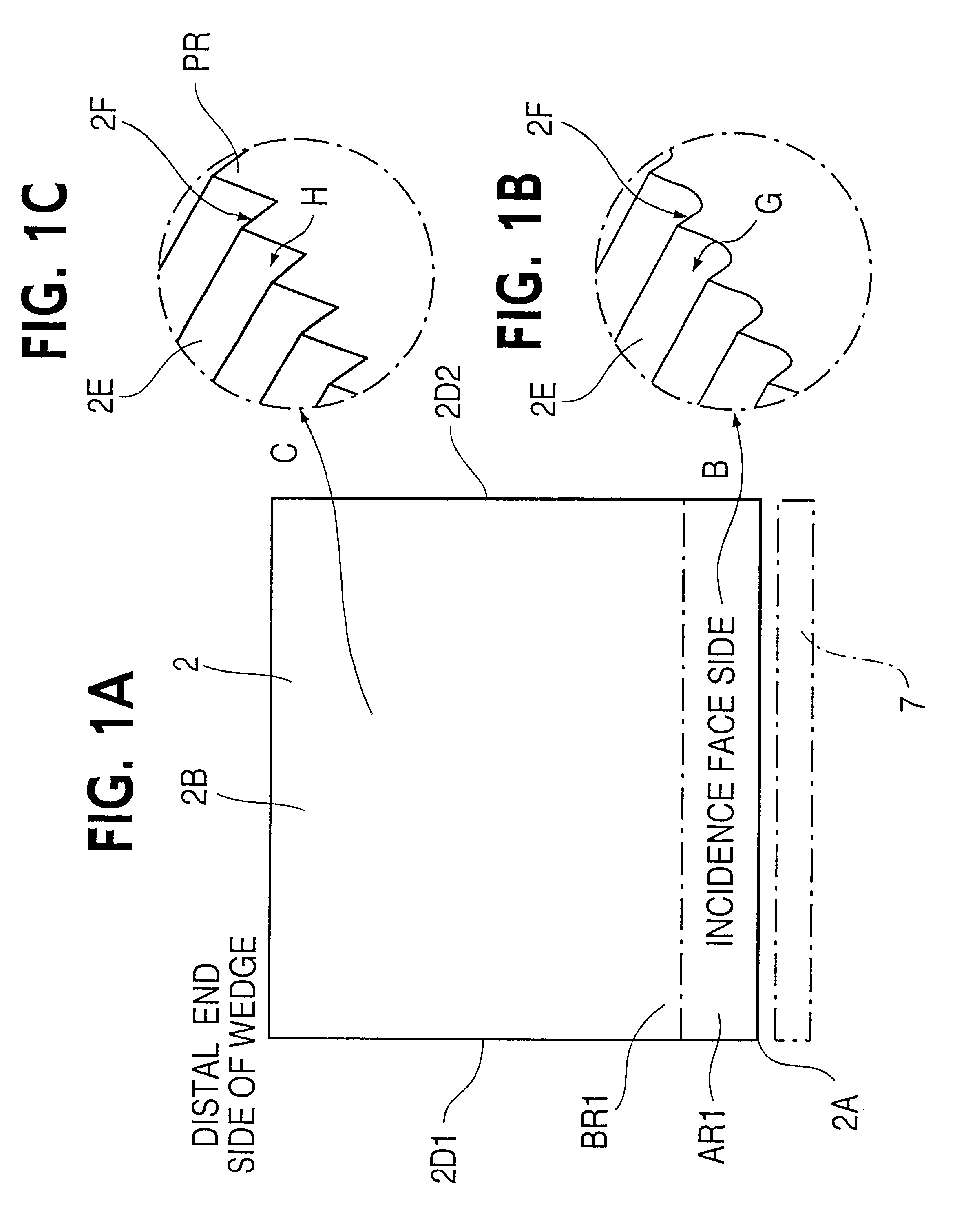
FIG. 1 is a plan view of a light guide plate employed in the first embodiment. FIG. 2 is an exploded perspective view to outline an arrangement of the first embodiment.

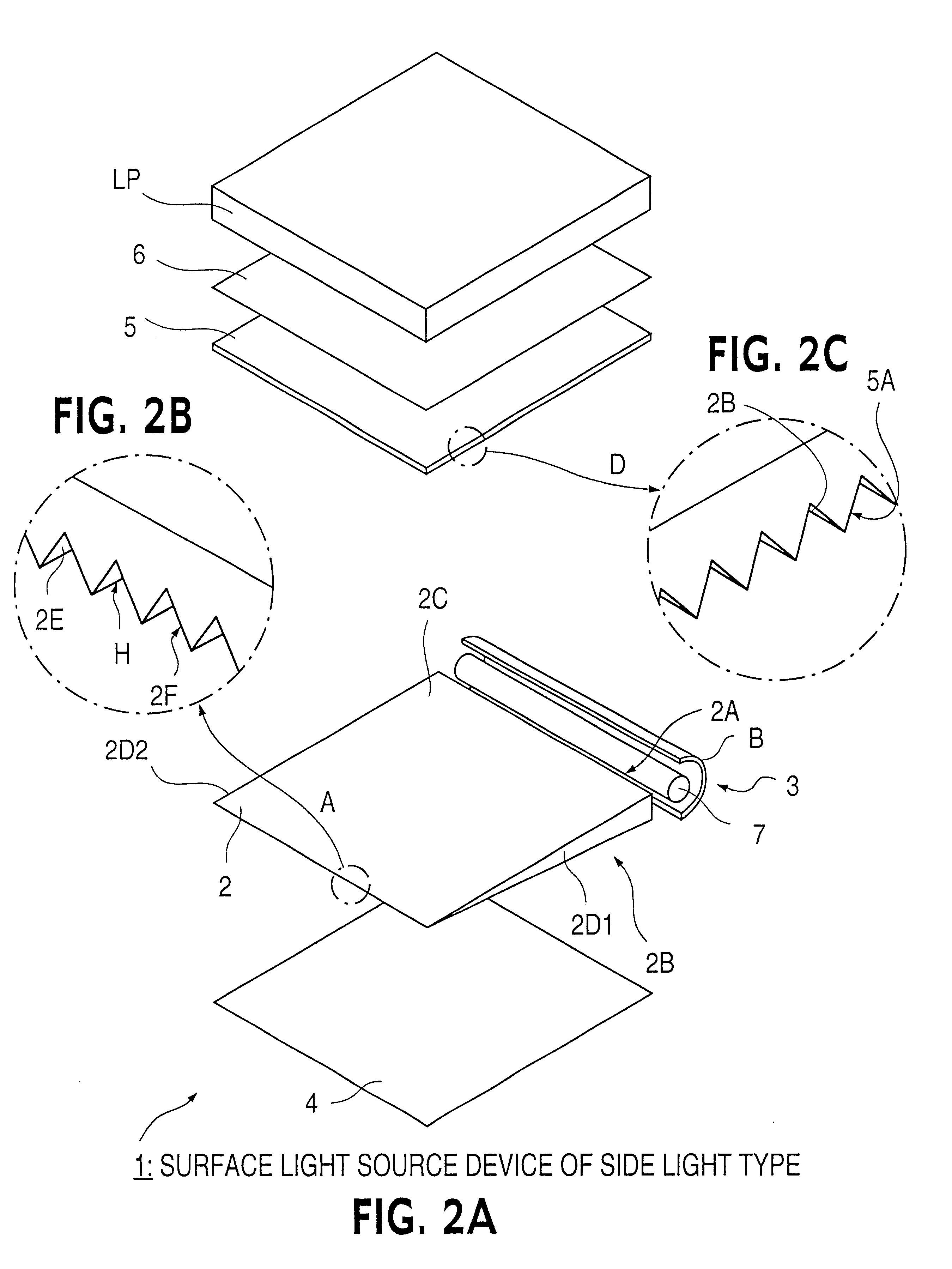
First, referring to FIG. 2, a liquid crystal display panel LP is disposed in front of a surface light source device of side light type 1 to provide a backlighting-type liquid crystal display. The liquid crystal display panel LP is supplied with illumination light outputted from the surface light source device 1. The surface light source device 1 comprises a light guide plate 2, primary light source 3, reflection sheet 4, prism sheet 5 and a protection sheet 6. The reflection sheet 4, light guide plate 2, the prism sheet 5 and the protection sheet 6 are laminatedly arranged in order while the primary light source is disposed beside and in the vicinity of an incidence face (incidence end face) provided by a minor face of the light guide plate 2. These components are mounted and held in a frame, not s...

second embodiment

(2) Second Embodiment

The present embodiment employs a light guide plate 32 as shown in FIG. 9 instead of the light guide plate 2 as shown in FIG. 1 or 2. Except this, the present embodiment has the same structured as that of the first embodiment. Accordingly, repeating of common description such as that of the whole arrangement is omitted, and description is focused on structure and operation of the light guide plate 32.

The light guide plate 32 may be formed of an injection-molded transparent resin as the light guide plate 2. One of major faces 32B (back face and emission face) provides a prism cut surface.

As partially enlarged in FIG. 9 (arrows E, F), a great number of fine projection rows running in a direction approximately perpendicular to an incidence face 32A have pairs of slopes 32E, 32F which are connected to each other at skirt portions of the projection rows to provide valleys G, H. This gives a great number of fine valleys G, H running in a direction approximately perpend...


PUM

PropertyMeasurementUnit
vertical angleaaaaaaaaaa

Abstract

Cylindrically curved slopes successively inner-reflect illumination light which reaches a back face or emission face of a light guide plate via an upper edge of an incidence face. The curved slopes give the light diverse propagation directions after inner-reflection. This avoids the viewer from observing a strongly irradiated edge, thereby reducing reflective appearance. Inner-reflection by the curved slopes also gives diverse propagation directions to illumination light coming via other edges, thereby reducing reflective appearance. Curved surface profile is given to valleys involved in a great number of projection rows running in a direction approximately perpendicular to the incidence face, and may be further given to the projection rows. The valleys are provided with curved surface profile within a curved-surface-profile-giving-area around the incidence face or, in addition to this, around flank faces of the light guide plate. The curved surface profile varies gradually around a boundary of the curved-surface-profile-giving-area to avoid sudden profile changing which would bring undesirable effects.

Description

1. Field of InventionThe present invention relates to a light guide plate, surface light source device of side light type and liquid crystal display. More specifically, the invention relates to a light guide plate having a minor face to provide a side end face through which light is inputted and having a major face through which light is outputted, and to a surface light source device of side light type and liquid crystal display which employ the light guide plate.2. Related ArtIt has been known to apply a surface light source device of side light type to a device, for example, to a liquid crystal display for backlighting its liquid crystal display panel. This arrangement is suitable for giving the device a thin whole structure.In general, a surface light source device of side light type employs a rod-shaped light source like cold cathode tube as a primary light source which is disposed beside a light guide plate (plate-shaped light guide). The primary light source emits light illum...

Claims


Application Information

Patent Timeline
Patent Type & Authority Patents(United States)
IPC IPC(8): F21V8/00G02B6/00F21W101/14F21Y103/00G02F1/1335G02F1/13357
CPCG02B6/0038G02B6/0061G02B6/0088G02F1/1335
Inventor OHKAWA, SHINGO
Owner ENPLAS CORP
Why Eureka
Try Eureka