Eureka AIR delivers breakthrough ideas for toughest innovation challenges, trusted by R&D personnel around the world.

Organic light emitting display

a technology of light-emitting displays and organic materials, applied in the direction of electric lighting sources, electric light sources, solid-state devices, etc., can solve the problems of considerable higher manufacturing costs and disadvantages, and achieve the effect of preventing the generation of horizontal line-shaped spots

Active Publication Date: 2011-02-03
SAMSUNG DISPLAY CO LTD
View PDF3 Cites 11 Cited by
  • Summary
  • Abstract
  • Description
  • Claims
  • Application Information

AI Technical Summary

Benefits of technology

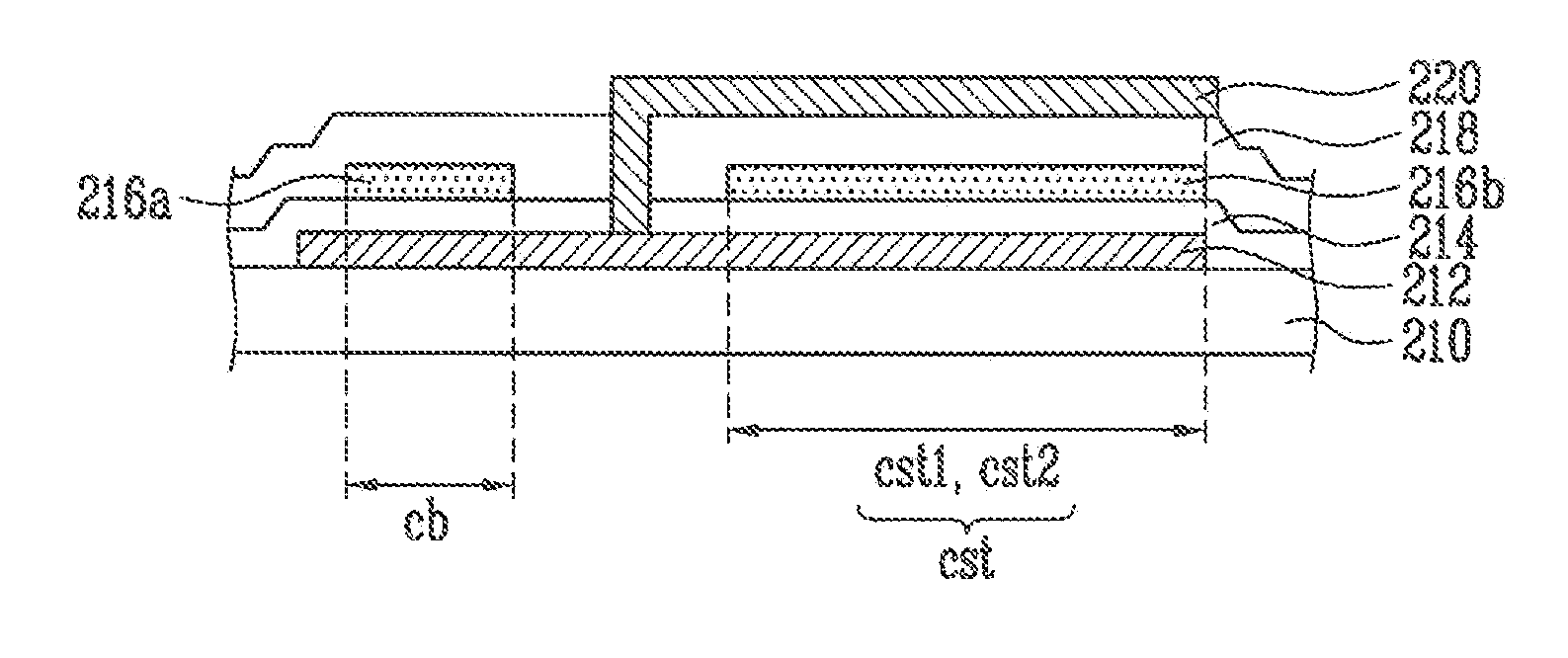
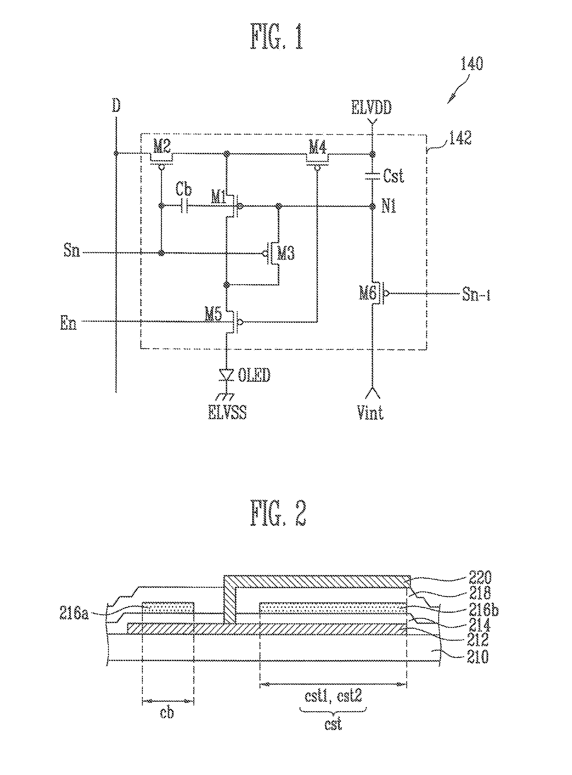
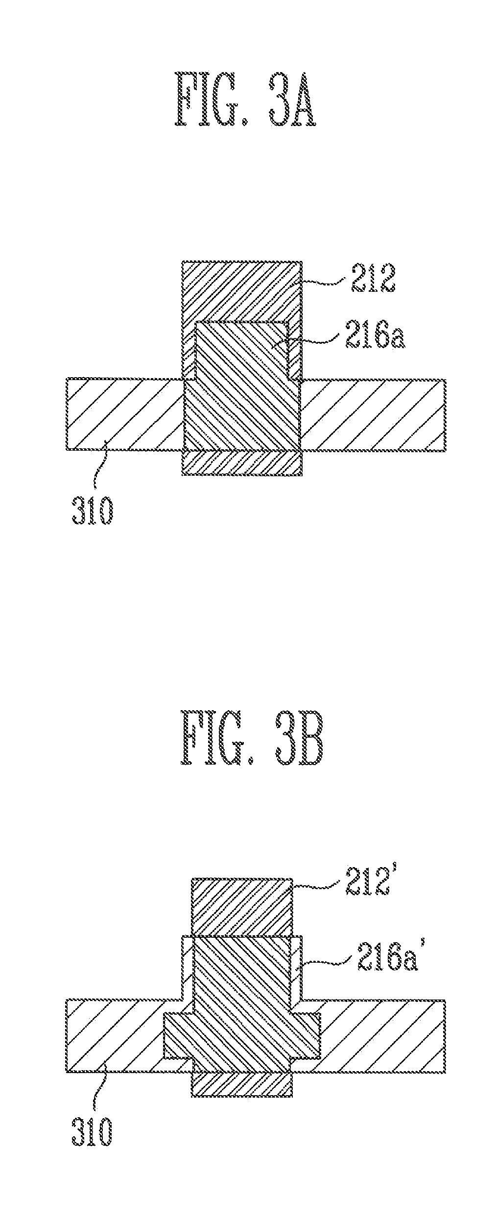
[0013]An embodiment of the invention provides an organic light emitting display that has the same area where the upper and lower electrodes of a capacitor are overlapped per adjacent pixels for respective pixels that constitute the organic light emitting display but implements the sizes of the upper and lower electrodes to be different, thereby preventing the display quality of horizontal line shaped spot generated due to the effects of a critical dimension (CD) distribution from being degraded.
[0017]With the embodiment as described above, the organic light emitting display has the same area where the upper and lower electrodes of a capacitor are overlapped per adjacent pixels for respective pixels that constitute the organic light emitting display but implements the sizes of the upper and lower electrodes to be different. Therefore, the above described embodiment of the invention has the advantage of preventing the display quality of horizontal line shaped spot generated from being degraded due to the effects of a critical dimension (CD) distribution.

Problems solved by technology

For example, in the case of a capacitor formed on the scan line for each pixel region, a problem arises in that a horizontal line shaped spot is generated according to the CD distribution generated in forming the electrode of the capacitor.
In order to reduce the effects of the CD distribution, there is a method to lower the tolerance of the mask, that is, to manufacture the mask more precisely, but this method is disadvantageous in view of considerably higher manufacturing costs.

Method used


Image

  • Organic light emitting display
  • Organic light emitting display
  • Organic light emitting display

Examples


Embodiment Construction

[0022]In the following detailed description, only certain exemplary embodiments of the present invention have been shown and described, simply by way of illustration. As those skilled in the art would realize, the described embodiments may be modified in various different ways, all without departing from the spirit or scope of the present invention. Accordingly, the drawings and description are to be regarded as illustrative in nature and not restrictive. In addition, when an element is referred to as being “on” another element, it can be directly on the other element or be indirectly on the other element with one or more intervening elements interposed in between. Also, when an element is referred to as being “connected to” another element, it can be directly connected to the other element or be indirectly connected to the other element with one or more intervening elements interposed in between. Hereinafter, like reference numerals refer to like elements.

[0023]Hereinafter, exempla...


PUM


Abstract

The general inventive concept relates to an organic light emitting display that has the same area where the upper and lower electrodes of a capacitor are overlapped for adjacent pixels, for respective pixels that constitute the organic light emitting display but implements the sizes of the upper and lower electrodes to be different. This thereby prevents the display quality of horizontal line shaped spot generated due to the effects of a critical dimension (CD) distribution from being degraded.

Description

CLAIM OF PRIORITY[0001]This application makes reference to, incorporates the same herein, and claims all benefits accruing under 35 U.S.C. §119 from an application earlier filed in the Korean Intellectual Property Office on 30 Jul. 2009 and there duly assigned Serial No. 10-2009-0069926.BACKGROUND OF THE INVENTION[0002]1. Field of the Invention[0003]The general inventive concept relates to an organic light emitting display, and more particularly, to an organic light emitting display that prevents the display quality of horizontal line shaped spot generated due to the effects of a critical dimension (CD) distribution from being degraded.[0004]2. Description of the Related Art[0005]Recently, flat panel displays (FPD), which solve weight and volume disadvantages of the cathode ray tube (CRT), and have the advantages of being compact and lightweight, have been spotlighted. Among flat panel displays, there are liquid crystal displays (LCD), organic light emitting diode displays (OLED), f...

Claims


Application Information

Patent Timeline
Patent Type & Authority Applications(United States)
IPC IPC(8): H01L51/52
CPCH01L27/3265H10K59/1216H05B33/26H10K50/813H10K50/822
Inventor LEE, KEUN-SOO
Owner SAMSUNG DISPLAY CO LTD
Why Eureka
Eureka Blog
Learn More