Liquid Crystal Display Device

a liquid crystal display and display device technology, applied in the field of liquid crystal display devices, can solve the problems of difficult optical compensation of liquid crystal cells perfectly, lowering display quality, and not being able to avoid grayscale inversions generating at under areas, so as to reduce color variation generating, improve contrast, and reduce the effect of displaying quality

Active Publication Date: 2008-09-11
FUJIFILM CORP
View PDF9 Cites 10 Cited by
  • Summary
  • Abstract
  • Description
  • Claims
  • Application Information

AI Technical Summary

Benefits of technology

[0021]According to the present invention, it is possible to improve the contrast when LCD is observed in an oblique direction, especially in a 45° oblique direction, and the angle between two transmission axes of two polarizing plates is out of 90°, and to reduce the color variation generating depending on the viewing angle in a black state, without lowering displaying qualities in the frontal direction.

Problems solved by technology

However, it is extremely difficult to optically compensate liquid-crystal cells perfectly even if the film formed of hybrid-aligned liquid-crystal molecules are used, and it is not possible to avoid grayscale inversions generating at under areas of images.
Consequently, small light leakage generating at opposing corners in the black state while being observed in an oblique direction has come to the surface as a cause of lowering displaying-quality.
Many of the proposed methods are methods to improve viewing angles by counteracting the birefringence of liquid crystal in the cell, and cannot sufficiently prevent light leakage generating while the liquid-crystal displays are observed in oblique direction, or, in other words, the polarizing axes are out of orthogonal alignment.
Some of the proposed methods are for lowering such light leakage and, however, even if such methods are employed, it is extremely difficult to optically compensate the liquid-crystal cell perfectly.
Known optical compensatory sheets used for an IPS mode or a FFS mode liquid-crystal cell are thick since they consists of plural films, and this is disadvantageous for thinning of liquid-crystal displays.

Method used


Image

  • Liquid Crystal Display Device
  • Liquid Crystal Display Device
  • Liquid Crystal Display Device

Examples


example 1

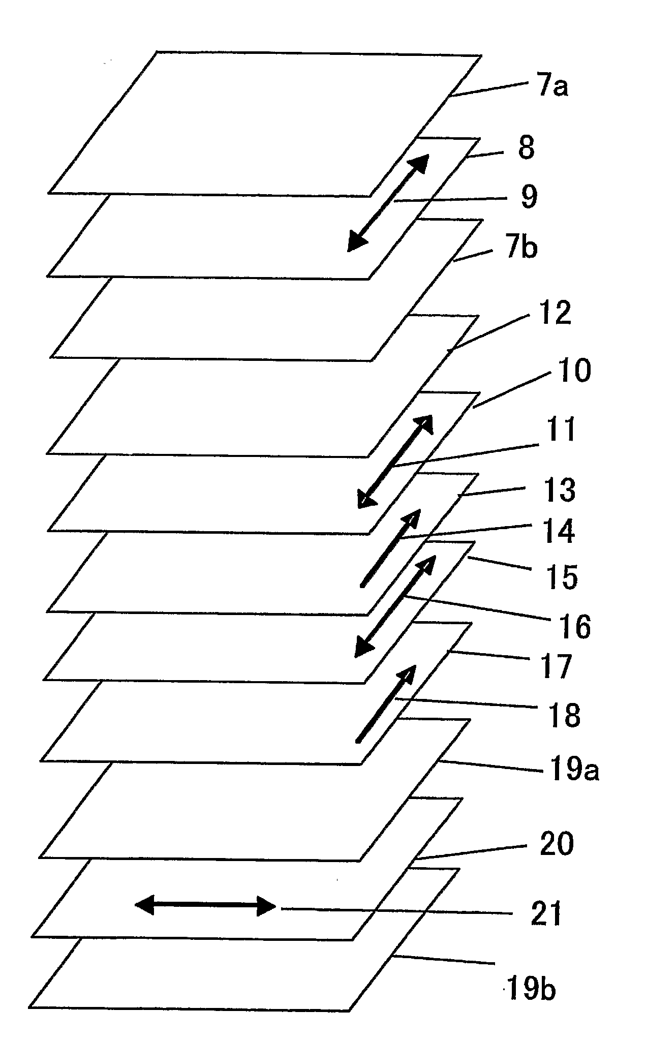
[0140]The first retardation region No. 1 as prepared was stuck on the side of the polarizing plate protective film No. 2 of the polarizing plate A using an acrylic adhesive in such a manner that the transmission axis of the polarizing film and the slow axis of the first retardation region No. 1 were intersected perpendicularly to each other. Further, the second retardation region No. 1 was stuck thereonto using an acrylic adhesive.

[0141]This laminate was stuck on one side of the IPS mode liquid crystal cell No. 1 as prepared previously in such a manner that the transmission axis of the polarizing plate was parallel to the rubbing direction of the liquid crystal cell (that is, the slow axis of the first retardation region No. 1 was intersected perpendicularly to the slow axis of the liquid crystal molecule of the liquid crystal cell in a black state) and that the side of the second retardation region No. 1 was faced at the liquid crystal cell side.

[0142]Subsequently, the polarizing p...

example 2

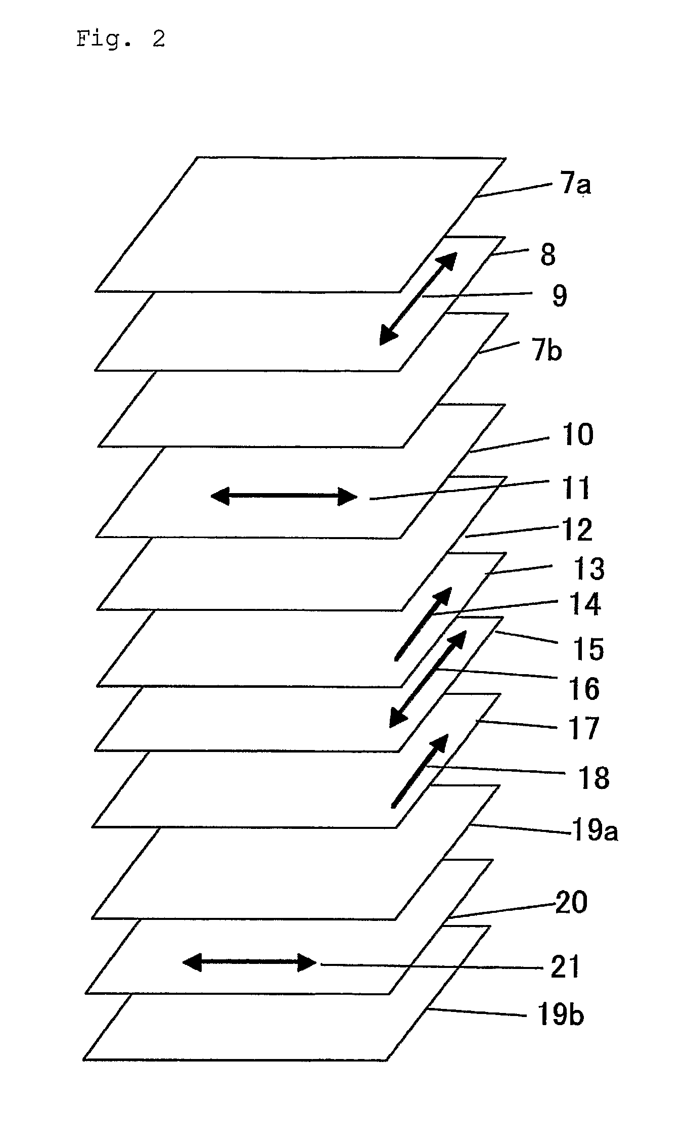
[0144]The first retardation region No. 2 as prepared was stuck on the side of the polarizing plate protective film No. 1 of the polarizing plate B using an acrylic adhesive in such a manner that the transmission axis of the polarizing film and the slow axis of the first retardation region 2 were intersected perpendicularly to each other. Further, the second retardation region No. 1 was stuck thereonto using an acrylic adhesive.

[0145]This laminate was stuck on one side of the IPS mode liquid crystal cell No. 1 as prepared previously in such a manner that the transmission axis of the polarizing plate was parallel to the rubbing direction of the liquid crystal cell (that is, the slow axis of the first retardation region No. 2 was intersected perpendicularly to the slow axis of the liquid crystal molecule of the liquid crystal cell in a black state) and that the side of the second retardation region No. 1 was faced at the liquid crystal cell side.

[0146]Subsequently, the polarizing plate...

example 3

[0147]The first retardation region No. 3 as prepared was stuck on the polarizing plate D using an acrylic adhesive in such a manner that the transmission axis of the polarizing film and the slow axis of the first retardation region No. 3 were parallel to each other. In this construction, FUJITAC TD80UF having an Re of 2 nm and an Rth of 48 nm which is the protective film of the polarizing plate D is corresponding to the second retardation region.

[0148]This laminate was stuck on one side of the IPS mode liquid crystal cell No. 1 as prepared previously in such a manner that the transmission axis of the polarizing plate was parallel to the rubbing direction of the liquid crystal cell (that is, the slow axis of the first retardation region No. 3 was parallel to the slow axis of the liquid crystal molecule of the liquid crystal cell in a black state) and that the side of the first retardation region No. 3 was faced at the liquid crystal cell side.

[0149]Subsequently, the polarizing plate ...


PUM

PropertyMeasurementUnit
thicknessaaaaaaaaaa
thicknessaaaaaaaaaa
thicknessaaaaaaaaaa

Abstract

A novel liquid crystal display device is disclosed. The liquid crystal display device comprises a first polarizing film, a first retardation area with an Re of 70 to 330 nm and a value of Nz of not less than 0 to less than 0.5 and a slow axis perpendicular to a transmission axis of the first polarizing film; a second retardation region with an Re of not greater than 50 nm and an Rth of 10 to 140 nm; and a liquid crystal cell comprising a liquid crystal layer with a slow axis in a black state parallel to the transmission axis of the first polarizing film; and a second polarizing film in this order.

Description

TECHNICAL FIELD[0001]The present invention relates to a liquid crystal display device and to a ferroelectric liquid crystal display device, an antiferroelectric liquid crystal display device and a liquid crystal display device employing in-plane switching mode which displays images by being applied the crosswise field to nematic liquid crystals aligned in the horizontal direction.RELATED ART[0002]TN-mode liquid-crystal displays have been used widely. The TN-mode DLC usually comprises two polarizing plates and a liquid-crystal layer formed of twisted-orientated nematic liquid crystal sandwiched in between the polarizing plates, and the field is applied in an orthogonal direction to the substrate of the liquid-crystal layer. In the TN-mode, liquid-crystal molecules tilt against the substrate in a black state, and thus, birefringence due to such an orientation of the liquid-crystal molecules generates when being observed in an oblique direction, and light leakage occurs. In order to so...

Claims


Application Information

Patent Timeline
Patent Type & Authority Applications(United States)
IPC IPC(8): G02F1/13363G02B5/30G02F1/1335G02F1/139G02F1/1343
CPCG02F1/134363G02F1/133634G02F1/13363G02F1/1335G02F1/139
Inventor ICHIHASHI, MITSUYOSHINISHIURA, YOUSUKENISHIURA, TAKAKOSASADA, YASUYUKI
Owner FUJIFILM CORP
Why Eureka
Try Eureka