Display device, drive method thereof, and electronic device

a technology of electronic devices and drive methods, applied in the direction of electric digital data processing, instruments, computing, etc., can solve the problems of insufficient operation of dynamic luminance value control, deterioration of display quality in low electric power consumption modes, etc., to prevent deterioration of display quality and reduce electric power consumption

Active Publication Date: 2014-01-16
SHARP KK
View PDF3 Cites 11 Cited by
  • Summary
  • Abstract
  • Description
  • Claims
  • Application Information

AI Technical Summary

Benefits of technology

[0028]As described above, a display device of the present invention includes: a scanning line driving circuit for sequentially selecting a plurality of scanning signal lines included in a screen which is made up of a plurality of pixels arranged in a matrix pattern; a signal line driving circuit for sequentially supplying data signals via data signal lines to pixels connected to a selected one of the plurality of scanning signal lines, the data signal lines corresponding to the respective pixels; a driving control section for driving the scanning line driving circuit and the signal line driving circuit by providing (i) a scanning period during which one (1) screen is scanned and (ii) a pause period which follows the scanning period and during which all the plurality of scanning signal lines are in a non-scanning state; a detection data obtaining section for obtaining detection data on an external light intensity; and a luminance control signal outputting section for outputting, at least during the pause period, a luminance control signal for adjusting, in accordance with the detection data obtained by the detection data obtaining section, a luminance of light to be emitted to the screen.
[0029]As described above, a method for driving a display device of the present invention includes the steps of: (a) driving the scanning line driving circuit and the signal line driving circuit by providing (i) a scanning period during which one (1) screen is scanned and (ii) a pause period which follows the scanning period and during which all the plurality of scanning signal lines are in a non-scanning state; (b) obtaining detection data on an external light intensity; and (c) outputting, at least during the pause period, a luminance control signal for adjusting, in accordance with the detection data obtained in the step (b), a luminance of light to be emitted to the screen.
[0030]As described above, an electronic device of the present invention includes: the display device; a light detection section for outputting the detection data on the external light intensity; and a light emitting section for obtaining the luminance control signal outputted by the luminance control signal outputting section of the display device, and adjusting, in accordance with the obtained luminance control signal, the luminance of the light to be emitted to the screen.
[0031]Therefore, it is possible to prevent a deterioration in display quality during the pause period while reducing electric power consumption.
[0032]Additional objects, features and strengths of the present invention will be made clear by the description below. Further, the advantages of the present invention will be evident from the following explanation in reference to the drawings.

Problems solved by technology

First, the case of a simple combination of the technique described in Patent Literature 2 and the luminance value control causes a side problem such that a display quality may deteriorate in a low electric power consumption mode (or in the pause period).
Thus, in a case where dynamic luminance value control (for example, active BL in which a luminance value of a backlight is adjusted in accordance with a result of detection of an external light intensity) is carried out, a function of the dynamic luminance value control cannot be sufficiently carried out.
This may cause a trouble such as a flicker in a display.

Method used


Image

  • Display device, drive method thereof, and electronic device
  • Display device, drive method thereof, and electronic device
  • Display device, drive method thereof, and electronic device

Examples


example 1

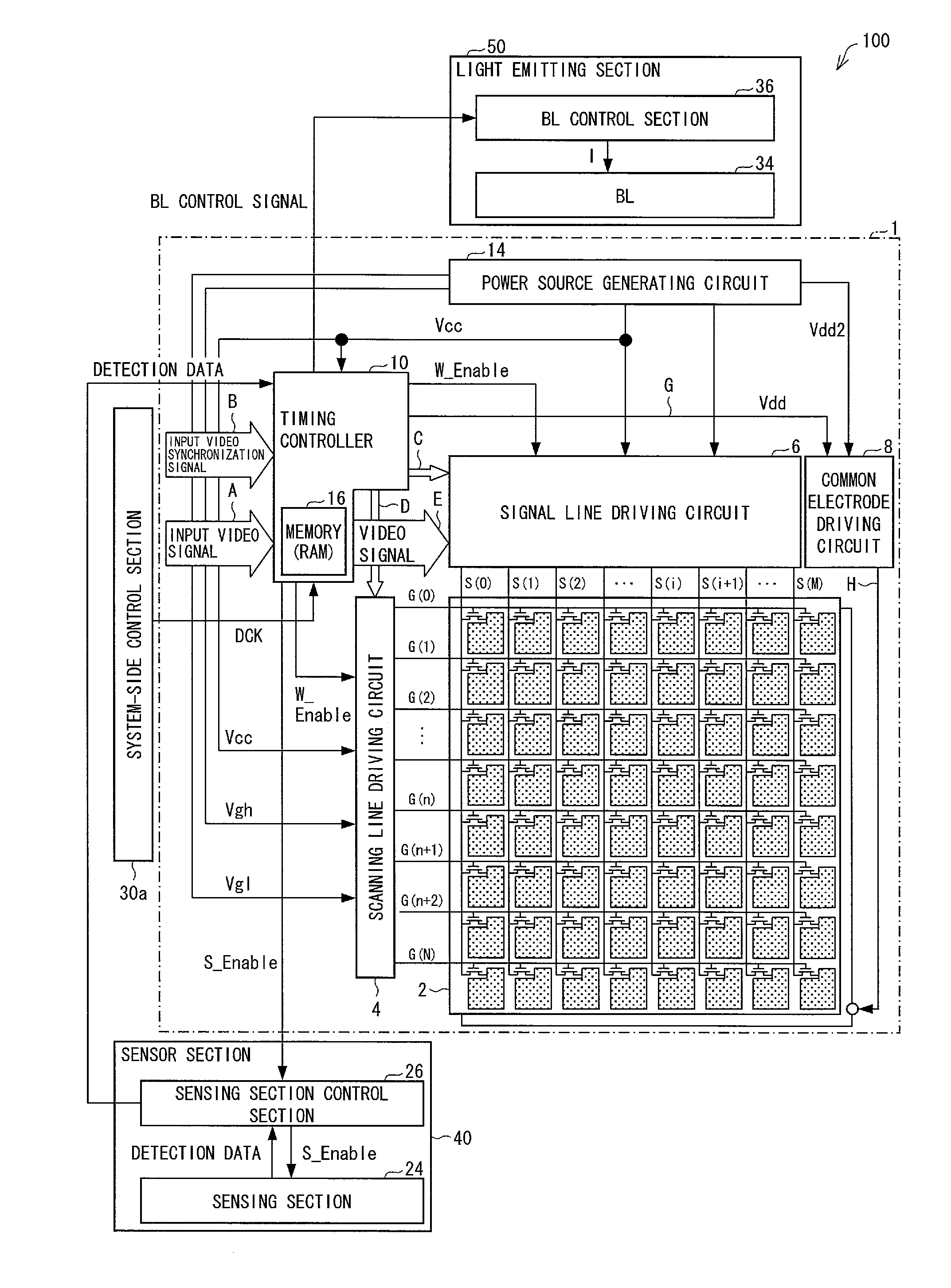
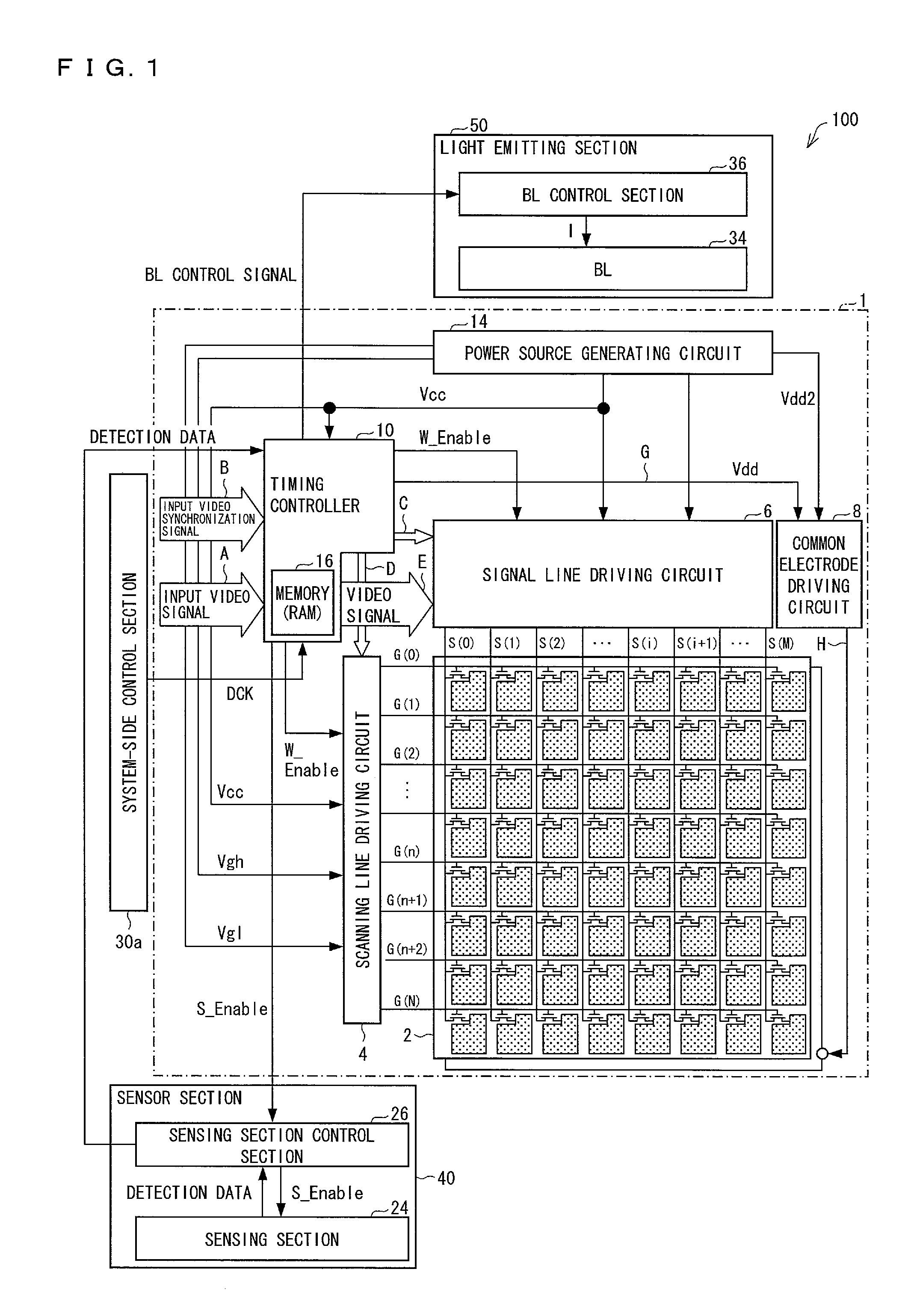
[0131]First, the following discusses, with reference to (a) and (b) of FIG. 5, an example (Example 1) of the main operations of the display systems 100 and 200.

[0132]As described earlier, the timing controller 10 drives the scanning line driving circuit 4 and the signal line driving circuit 6 by providing (i) the scanning period T1 (scanning frame) during which one (1) screen is scanned and (ii) the pause period T2 (pause frame) which follows the scanning period T1 and during which all the scanning signal lines are in a non-scanning state (a driving control step).

[0133]According to this, electric power consumption of the scanning line driving circuit 4, the electric power consumption increasing in proportion to a frequency at which the data signal is supplied, can be easily reduced by providing the pause period T2 following the scanning period T1 during which one (1) screen is rewritten.

[0134]The sensor section 40 detects the external light intensity (light detection step). Note tha...

example 2

[0146]Next, the following discusses, with reference to (a) and (b) of FIG. 6, another example (Example 2) of the main operations of the display systems 100 and 200.

[0147](a) and (b) of FIG. 6 each illustrate a case where the dimming period Td during which the BL control is carried out includes a plurality of frames.

[0148]According to the present example, during the dimming period Td including the plurality of frames, the BL control section 36 gradually adjusts a luminance of backlight for each of the plurality of frames included in the dimming period Td.

[0149]Note that according to the examples of (a) and (b) of FIG. 6, an external light intensity gradually increases (or gradually decreases) and thus the luminance of the backlight is also increased (or gradually decreased).

[0150]Meanwhile, for example, in a case where during the dimming period Td, the external light intensity gradually increases (or gradually decreases) and then gradually decreases (or gradually increases), the lumi...

example 3

[0152]Next, the following discusses, with reference to (a) and (b) of FIG. 7, and FIG. 8, a further example (Example 3) of the main operations of the display systems 100 and 200.

[0153](a) and (b) of FIG. 7, and FIG. 8 each illustrate a case where the dimming period Td during which the BL control is carried out includes a plurality of frames.

[0154]According to the present example, in order that the gray scale value control is carried out together with the BL control during the dimming period Td during which the BL control is carried out, the dimming period Td is interrupted by a new scanning period (an interrupt scanning period or an interrupt scanning frame).

[0155]According to the configuration, it is possible to rewrite (refresh) a display in the interrupt scanning frame. Thus, the configuration makes it possible to set a higher refresh rate than a case where no interrupt scanning frame is provided. Therefore, it is possible to prevent a flicker which easily occurs when the refresh...


PUM


Abstract

A display device includes: a timing controller (10) for driving a scanning line driving circuit (4) and a signal line driving circuit (6) by providing a scanning period (T1) and a pause period (T2) which follows the scanning period (T1); a data analyzing section (101) for obtaining detection data on an external light intensity; and a BL luminance setting section (104) for outputting, at least during the pause period (T2), a BL control signal for adjusting, in accordance with the detection data obtained by the data analyzing section (101), a luminance of light to be emitted to a screen.

Description

TECHNICAL FIELD[0001]The present invention relates to (i) a display device for displaying an image, a moving image, or the like, (ii) a method for driving the display device, and (iii) an electronic device which includes the display device.BACKGROUND ART[0002]In recent years, display devices have been extensively used which are thin, light, and low in electric power consumption, and are typified by liquid crystal display devices. Such display devices have been popularly provided in, for example, mobile phones, smart phones, and laptop personal computers. In addition, development and widespread use of electric paper which is a thinner display device are expected to be accelerated in the future. Under such circumstances, reducing electric power consumption in various kinds of display devices is a common object at present.[0003]A method in which peripheral circuits such as a control circuit and a driving circuit of a display device are stopped (intermittently driven) is known as a firs...

Claims


Application Information

Patent Timeline
Patent Type & Authority Applications(United States)
IPC IPC(8): G09G3/36
CPCG09G3/3674G09G3/3611G09G3/3406G09G2310/08G09G2320/0271G09G2320/064G09G2320/0646G09G2330/021G09G2340/0435G09G2360/144G02F1/133G09G3/36G09G3/3426G09G3/3648
Inventor TAKAHASHI, KOHZOHSAITOH, KOHJIYAMATO, ASAHINAKANO, TAKETOSHIYANAGI, TOSHIHIROFUJIOKA, AKIZUMINAKATA, JUN
Owner SHARP KK
Why Eureka
Try Eureka