PLL circuit having a variable output frequency

a phase lock loop and output frequency technology, applied in the direction of pulse automatic control, oscillation generator, angle modulation details, etc., can solve the problem of difficult to achieve accurate oscillation frequency

Inactive Publication Date: 2003-07-01
NEC CORP
View PDF7 Cites 21 Cited by
  • Summary
  • Abstract
  • Description
  • Claims
  • Application Information

AI Technical Summary

Benefits of technology

In view of the above, it is an object of the present invention to provide a practical PLL circuit which is capable compensating the deviation of the output frequency caused by a temperature fluctuation and variance or scattering of the characteristics of the components in the VCO, whereby the VCO can be integrated in a LSI constituting the PLL circuit substantially without loosing an accuracy of the output frequency.

Problems solved by technology

The reference frequency oscillator 46 is not integrated in the LSI because the crystal oscillator cannot be installed in the LSI and an accurate frequency oscillator having a temperature-compensated output frequency cannot be manufactured without the crystal oscillator.
The VCO 41 is not integrated in the LSI in the prior art because the output frequency of the VCO significantly fluctuates due to the fluctuation of the ambient temperature and the variance or scattering of the characteristics of the components thereof and an adjustment of the output frequency in the LSI for compensating the temperature fluctuation etc. to obtain an accurate oscillation frequency is difficult to achieve.

Method used


Image

  • PLL circuit having a variable output frequency
  • PLL circuit having a variable output frequency
  • PLL circuit having a variable output frequency

Examples


first embodiment

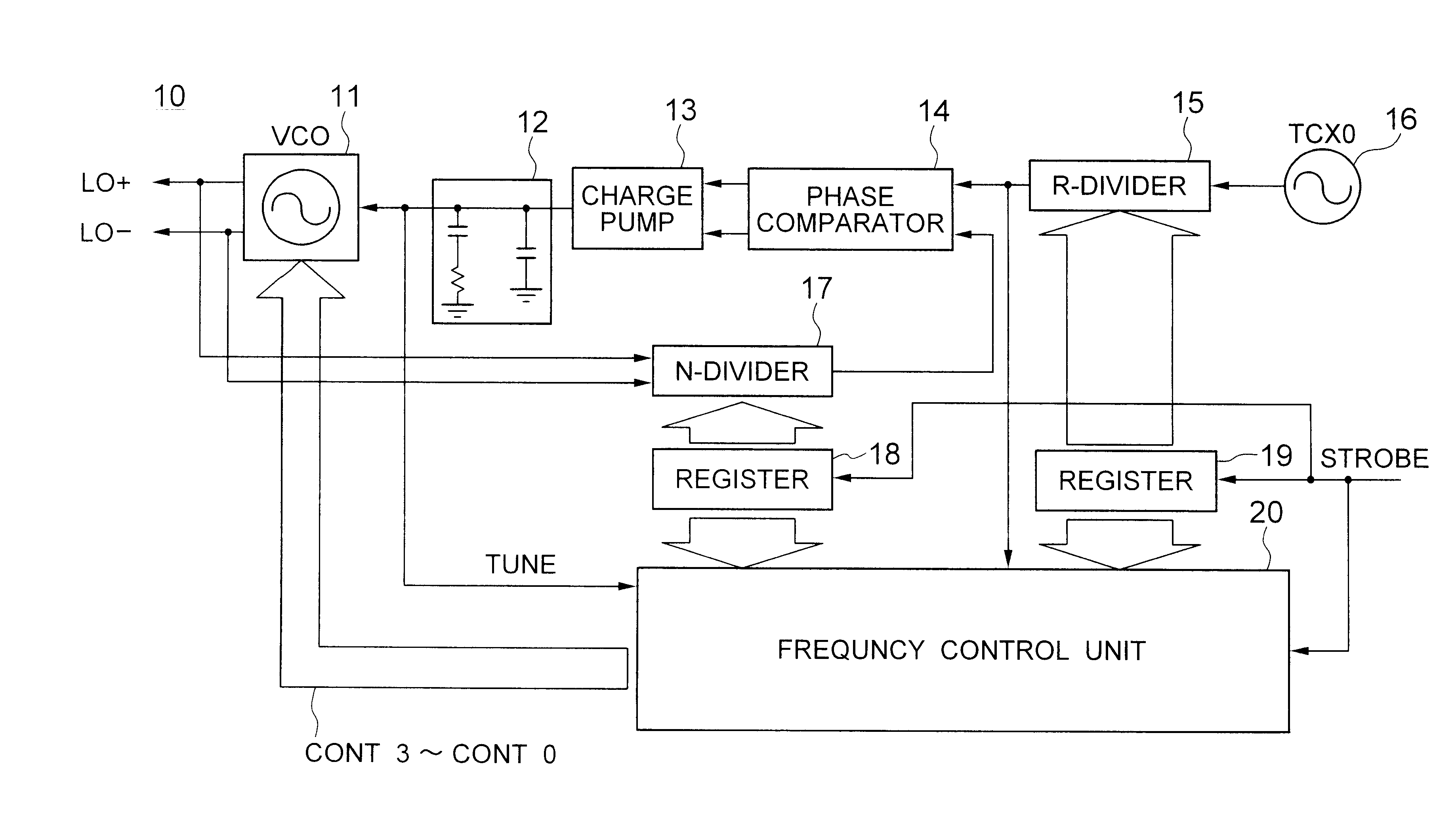
Referring to FIG. 6, a PLL circuit, generally designated by numeral 10, according to the present invention includes a VCO 11, an N-divider 17 for dividing the output signal from the VCO 41 by a number of N, a reference frequency oscillator 16, an R-divider 15 for dividing the reference frequency by a number of R, a register 18 for storing the number N, a register 19 for storing the number R, a phase comparator 14 for comparing the phase of the N-divided frequency signal output from the N-divider 18 against the phase of the R-divided frequency signal output from the R-divider 19, a charge pump 13 for receiving the output from the phase comparator 14, a loop filter 12 for passing the low-frequency component of the output from the charge pump 13 to generate a tune signal for the VCO 11, and a frequency control unit 20 for detecting the deviation of the output oscillation frequency of the VCO 11 from a specified frequency to control the oscillation frequency based on the detected deviat...

second embodiment

Referring to FIG. 10, a frequency control unit 20A in a PLL circuit according to the present invention includes a signal processor 34, and an analog-to-digital (A / D) converter 35. The tune voltage from the loop filter 12 in FIG. 6 is fed to the A / D converter 35 to be delivered to the signal processor 34 as a digital signal.

The data of numbers N and R stored in the registers 18 and 19 are directly fed to the signal processor 34. The signal processor 34 performs processing such as shown in FIG. 9, similarly to the frequency control unit of FIG. 3.

The PLL circuits according to the above embodiments compensate the deviation of the oscillation frequency caused by a temperature fluctuation and variance or scattering of the electronic components of the PLL circuits. Thus, the PLL circuit of the present invention can be integrated in a LSI without loosing an accuracy of the output oscillation frequency.


PUM


Abstract

A phase locked loop (PLL) circuit includes a voltage controlled oscillator (VCO) having a parallel resonant circuit including a first capacitance implemented by a reverse-biased diode and a second capacitance implemented by MOS capacitors. Upon lock-in of the oscillation frequency with respect to the reference frequency, whether the oscillation frequency has a deviation is examined based on the tune voltage controlling the first variable capacitance. If a deviation is observed due to a temperature fluctuation etc., the control voltage for the second variable capacitance is corrected for compensating the deviation.

Description

(a) Field of the InventionThe present invention relates to a phase locked loop (PLL) circuit having a variable output frequency and, more particularly, to an improvement of such a PLL circuit to have an adjustable output frequency.(b) Description of the Related ArtPLL circuits are used in a variety of equipment for generating a local oscillation frequency. The PLL circuit should have lower dimensions and be manufactured at a lower cost by, for example, reducing the number of electronic components thereof, in view that the PLL circuit is now installed in a mobile telephone or a GPS receiver which is ever requested to have a lower weight and smaller dimensions.FIG. 1 shows a conventional PLL circuit, which includes a VCO 41, an N-divider 47 for dividing the output signal from the VCO 41 by a number of N to output an N-divided frequency signal, a reference frequency oscillator 46, an R-divider 45 for dividing the reference frequency by a number of R to output an R-divided frequency sig...

Claims


Application Information

Patent Timeline
Patent Type & Authority Patents(United States)
IPC IPC(8): H03L7/099H03L7/10H03L7/08H03L7/16H03L7/18H03L7/095H03L7/187
CPCH03L7/099H03L7/10H03L7/18H03L7/095H03L7/104H03L7/08
Inventor ICHIHARA, MASAKI
Owner NEC CORP
Why Eureka
Try Eureka