Bionic automatic vision and line of sight control system and method

a technology of applied in the field of bionic automatic vision and line of sight control system and method, can solve the problems of multiple cameras not being able to simultaneously position and track the same object, unable to follow the moving speed of themselves or the moving speed of the object, and low tracking speed, etc., to achieve automatic sending out different levels of alarms and low cost

Active Publication Date: 2007-09-18
ANHUI EYEVOLUTION TECH CO LTD
View PDF7 Cites 19 Cited by
  • Summary
  • Abstract
  • Description
  • Claims
  • Application Information

AI Technical Summary

Benefits of technology

[0003]The object of the present invention is to provide an bionic automatic vision and line of sight control system, wherein the control principle of the nerve system of human oculomotor system was used to obtain the automatic control system and automatic control method to control the movements of the cameras, in order to accurately, quickly and precisely detect the object position and track the object by the line of sight, by reducing the deviation of camera's line of sight caused by the strong and wide range vibration and movement of camera itself, to ensure multiple cameras to detect and track the same object. Furthermore, it is possible to observe and monitor wide range, to watch surrounding objects and change into tracking other object while measuring, tracking and recording the object precisely.
[0008]2. The monocular or binocular can be cooperated with fixed wide angle camera or omnidirectional camera: For example, a wide angle lens camera or omnidirectional camera at an open space combine with one or more said monocular group constitute a monitor system, which can record the moving process of the objects within the monitored range. In addition, by transferring the location information of the monitored person from one monitor camera to another monitor camera at a different place, the person being monitored will not be mistaken as two different persons when this person moves from one place to another.
[0010]In addition, when this oculomotor system-is installed on a moving object (e.g. a car), the binocular system can be placed on a base that can rotate with multiple degree of freedom, similar to a human head. A pair of three degrees of freedom rotation acceleration transducers and a pair of three degrees of freedom translation acceleration transducers are located on each side of the “head” to measure the movement of the head and send signals directly to control forward feeding movement of the “eyeballs”, to enable the system to compensate the sight deviation caused by the movement of the object (similar to vestibulo-ocular reflex).
[0015]By using the above mentioned technical method, when the automatic vision and line of sight control system of the present invention are used in surveillance system, clear (precise) images of each person presented can be taken and recorded in turn, and each attendance's movement can be recorded real time, and automatically send out different levels of alarms. The present system can be used not only in fixed location indoor and outdoor surveillance, it can also be used in short distance low altitude on air surveillance, supplemental to a radar. In addition, the present system can be installed on many kinds of moving devices or equipments, such as car, train, airplane, boat, etc, by compensating the deviation of line of sight caused by severe and wide range movement of itself. Applying the control principle of the present invention to various robot's eyes, it will be possible to use household robot. Applying the control principle of the present invention, low cost camera (or fake eyeball) can be used as the eyes of the toys, and it will make the toys appear to be alive.

Problems solved by technology

When only these methods are used, the speed of tracking the object is very low, so it cannot follow the moving speed of itself or the moving speed of the object.
When each camera are controlled independently, multiple cameras cannot simultaneously position and track the same object.
When the tracked object needs to be zoomed in, other objects will escape from the viewing field and cannot be tracked.

Method used


Image

  • Bionic automatic vision and line of sight control system and method
  • Bionic automatic vision and line of sight control system and method
  • Bionic automatic vision and line of sight control system and method

Examples


Embodiment Construction

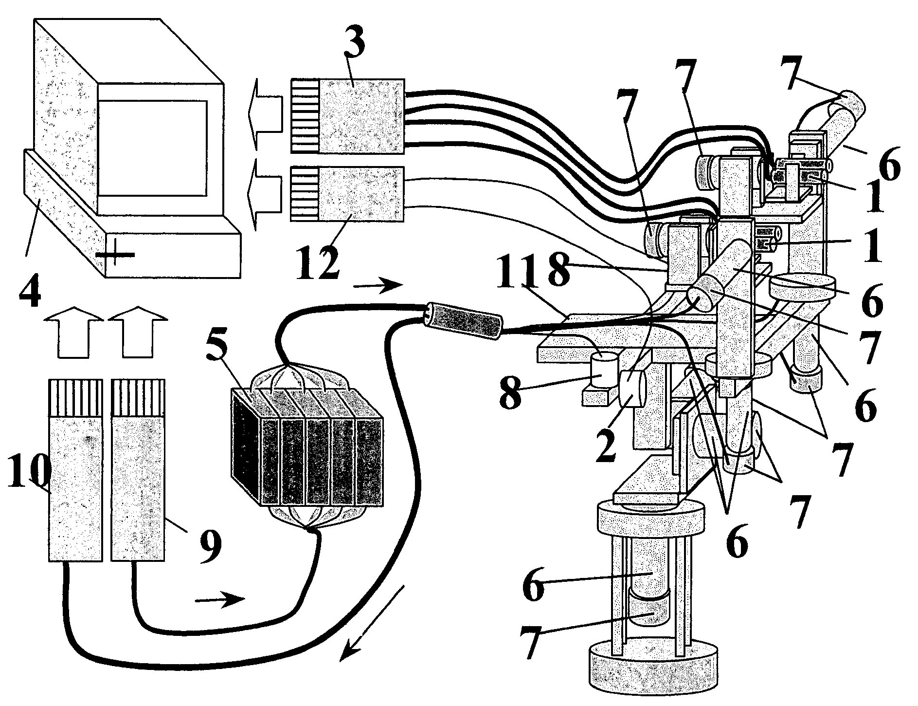
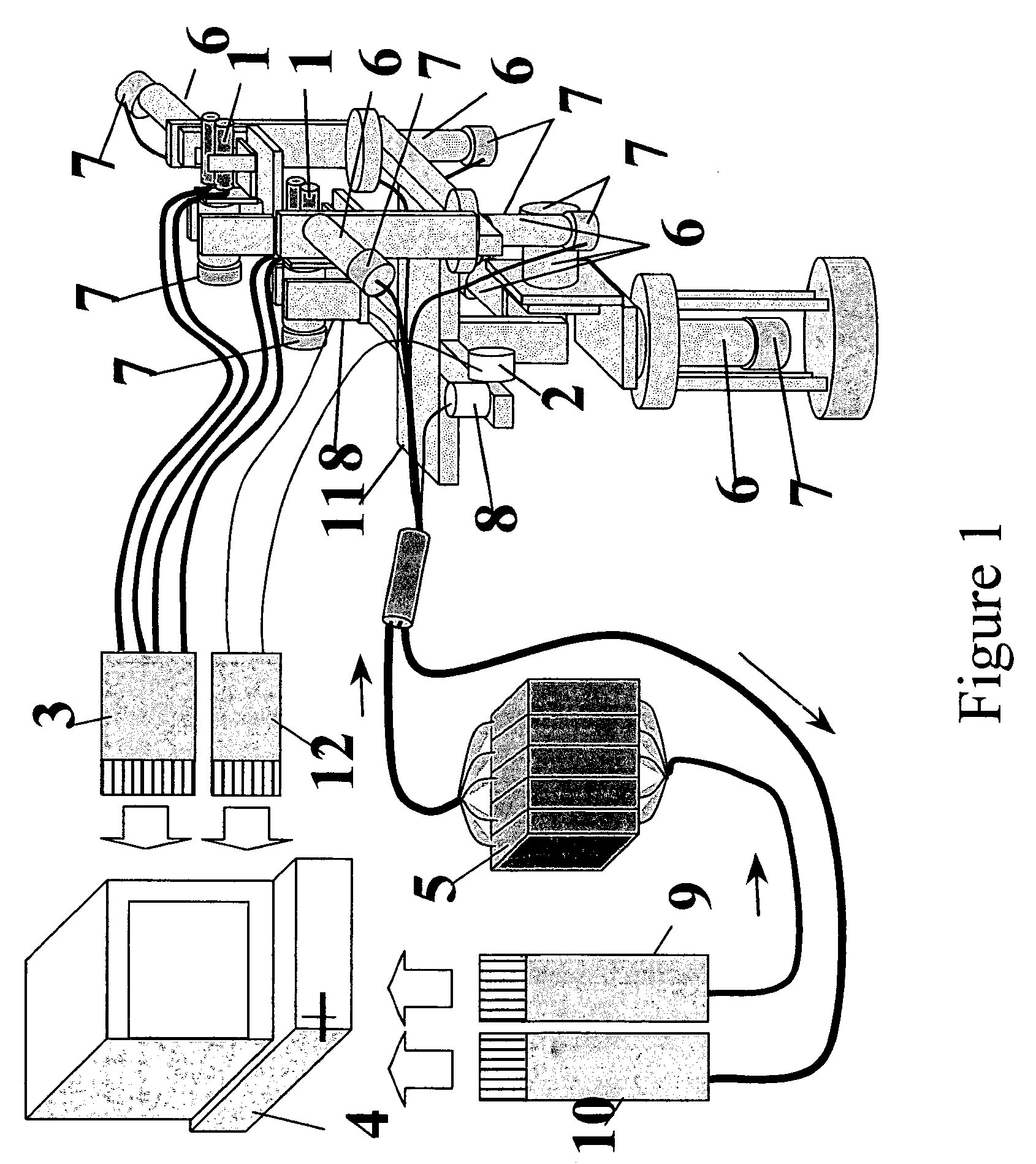
[0021]FIG. 1 shows the construction of the binocular vision and line of sight control system. Each eyeball consists of two cameras. One is a wide angle camera, and the other is a telephoto camera. The cameras are set parallel and adjacent to each other, the nearer the better. The oculomotor system has nine degrees of freedom. Each eyeball (camera set 1) has three degree of freedom (when necessary, one actuator can be eliminated), and the head (base 11) has three degree of freedom (it is possible to decrease or eliminate the number of degree of freedom).

[0022]Two camera sets 1 are installed on the base 11. The actuator control circuit works like this: the digital signal from the central controller is inputted into the D / A converter 9, and the analog signal converted by the D / A converter 9 is inputted into the actuator driving controller 5, and the driving controller 5 drives the actuators 6, while the rotation transducer 7 on the actuators 6 send the rotation angle signal of actuator...


PUM


Abstract

The present invention presents a bionic automatic vision and line of sight control system and method, wherein the system comprises multiple camera sets, wherein each camera set comprises one or more parallel camera with different shooting range, wherein each camera set is driven by one or three actuators, capable of rotating in two or three degree of freedom. The present system is capable of fast object positioning, high accuracy tracking and wide range compensation for line of sight deviation caused by the movement of the system. More specifically, the system can ensure two camera sets to position and track the same object at the same time. The present system not only can be used in various fixed places to monitor, protect and care taking, it can also be installed on various moving objects, such as cars, airplanes, boats, military equipments, and it can be used as eyes for various types of robots.

Description

FIELD OF INVENTION[0001]This application claims the benefit of prior filed Chinese application filed on Oct. 22, 2002 through international application PCT / CN2003 / 000872 filed on Oct. 20th, 2003 designating the United States of America. The present invention is related to bionic automatic vision and line of sight control system and method, also known as bionic robot eyes, which use cameras as the human eyes, wherein the motions of the cameras are controlled by principles of the nerve systems of human eyes. Therefore, the present invention has similar functions as the human eyes, it can perform object positioning, line of sight tracking, and compensate deviation of line of sight due to the movement of the system, especially because the current invention is capable of assuring simultaneous positioning of both eyes and following the same object, which leads to accurate measuring of the object position and distance, and obtain clear image of the object.DESCRIPTION OF RELATED ART[0002]Th...

Claims


Application Information

Patent Timeline
Patent Type & Authority Patents(United States)
IPC IPC(8): G03B17/00G03B35/08H04N7/18B25J9/16
CPCB25J9/1697H04N7/181G05B2219/37567G05B2219/40613
Inventor ZHANG, XIAOLINZHANG, GUANGRANG
Owner ANHUI EYEVOLUTION TECH CO LTD
Why Eureka
Try Eureka