Device on a portable cutting or sawing machine

a technology of cutting or sawing machine and device, which is applied in the direction of metal sawing accessories, working accessories, manufacturing tools, etc., can solve the problems of inability to control the flow of water at the same time, inability for the operator to read the setting of the valve during work, and inconvenient mounting, etc., to achieve the effect of cheap manufacturing and convenient mounting

Inactive Publication Date: 2003-07-15
HUSQVARNA AB
View PDF7 Cites 38 Cited by
  • Summary
  • Abstract
  • Description
  • Claims
  • Application Information

AI Technical Summary

Benefits of technology

To provide a valve which is easy to mount....

Problems solved by technology

This principle, however, has caused a number of inconveniences.
Because the valve is placed so that it is difficult to find, the operator must keep his left hand about the gripping part of the handle bow and manipulate the valve with his right hand, which means that he has to leave his hold of the rear handle and hence also leave his access of the controls for the driving machinery.
This in other words means that he cannot control the flow of water at the same time as he operates the machine.
This is a serious drawback because the type of work often makes it desirable to be able to vary the flow of water during operation, e.g. to increase the flow of water as the cutter blade successively cuts deeper and deeper in a workpiece and the kerf is being filled with cuttings.
The more or less hidden location of the valve also makes it impossible for the operator to read the setting of the valve during work.
Another inconvenience with today's devices, where the inl...

Method used


Image

  • Device on a portable cutting or sawing machine
  • Device on a portable cutting or sawing machine
  • Device on a portable cutting or sawing machine

Examples


Embodiment Construction

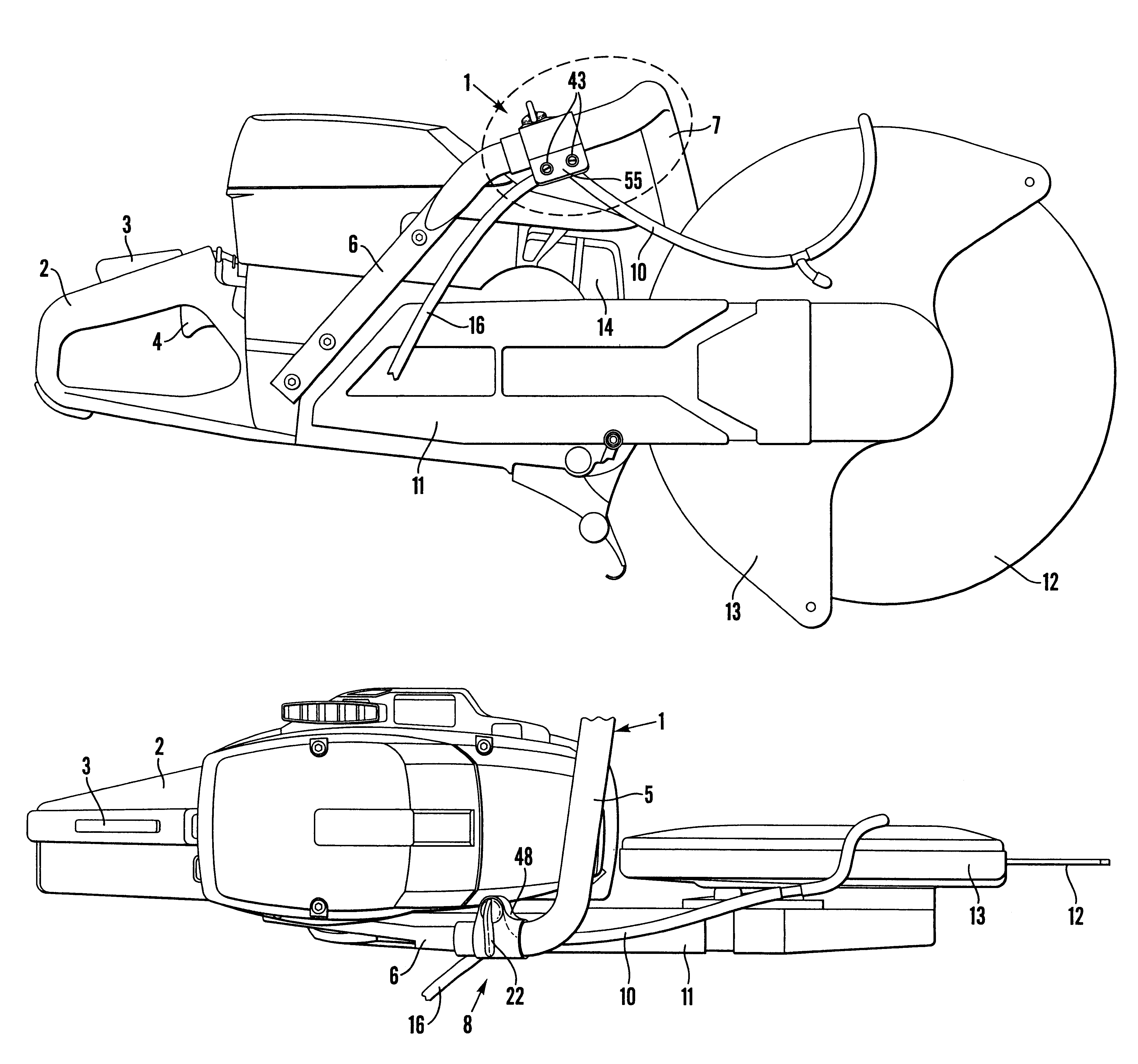
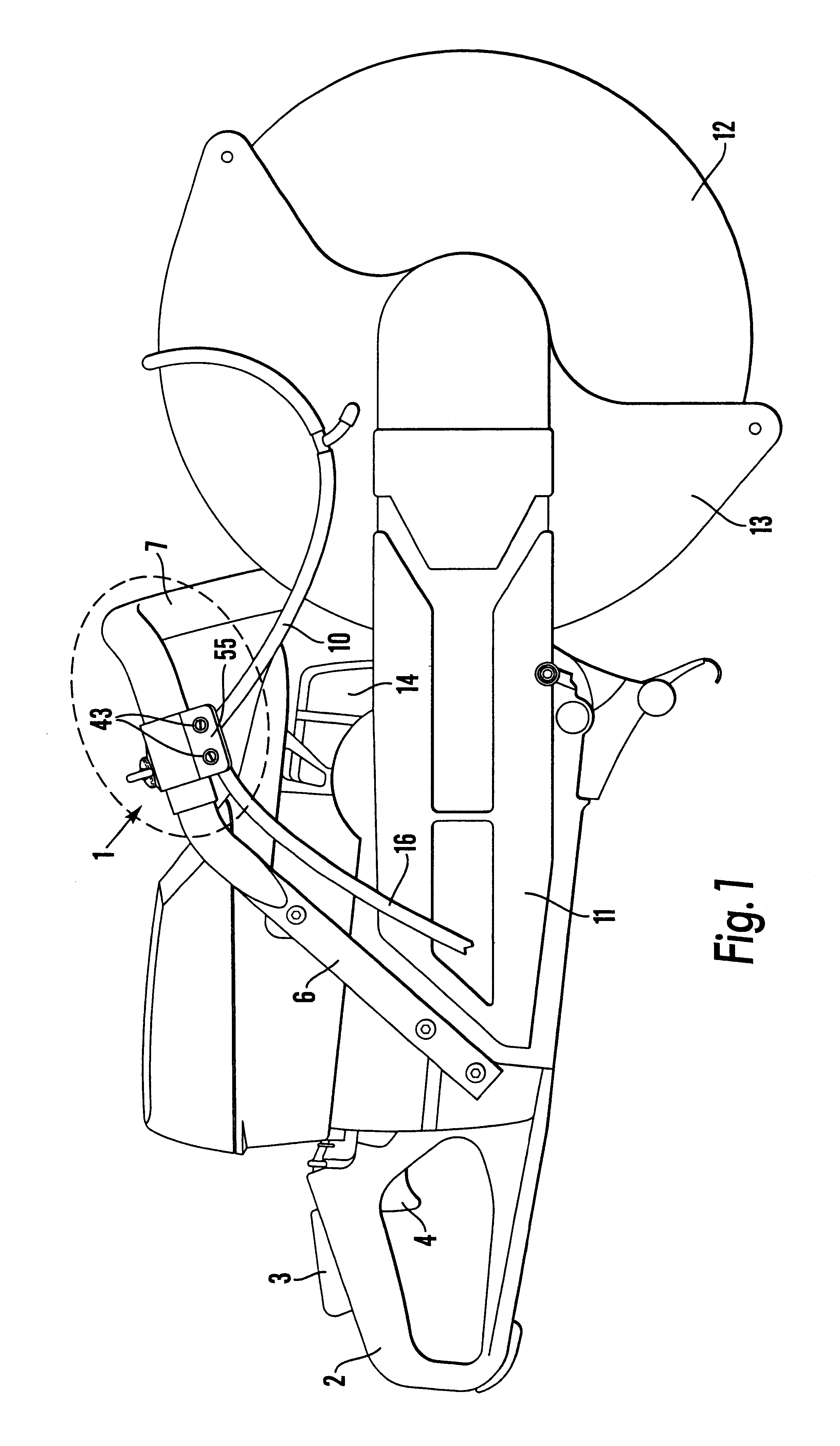
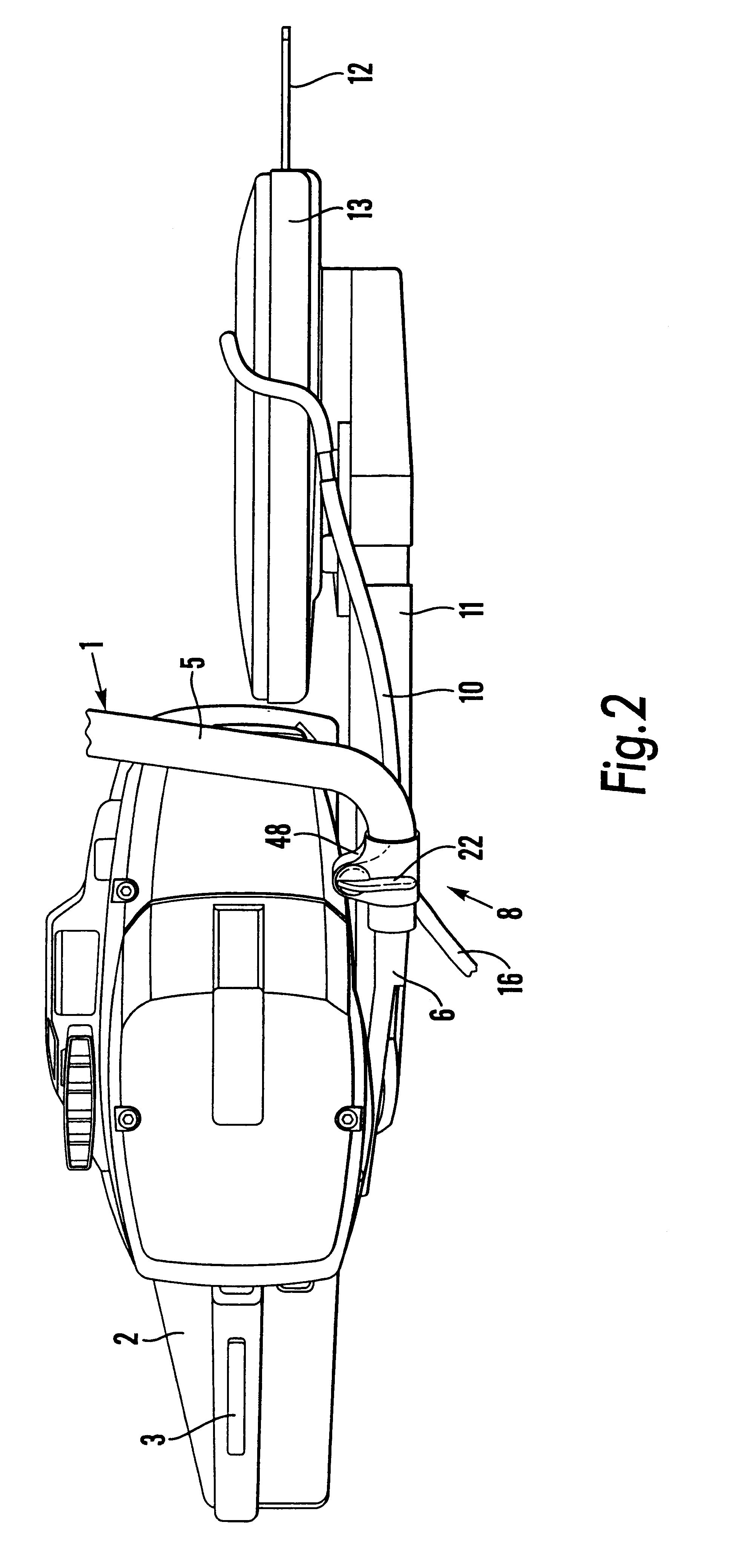
FIGS. 1 and 2 show a combustion engine powered cutting machine with a handle bow 1 and a rear handle 2. In connection to the rear handle there are controls 3, 4 for manoeuvering the driving machinery of the cutting machine by means of the fingers of the right hand of the operator at the same time as the operator is gripping about the rear handle 2. A front part 5 of the handle bow 1 is the normal gripping part of the handle bow, about which the operator keeps his left hand during operation. The gripping part 5 is conventionally horizontal. From the gripping part 5 a right hand side part 6 of the handle bow extends obliquely downwards and is fastened to the right hand side of the machine. A left hand side part 7 extends from the gripping part 5 and is fastened at the bottom of the machine under a blade holder 11. A cutting blade or cutting wheel is designated 12 and a muffler is designated 14.

A water valve 8 of the invention is mounted on the right hand side part 6 of the handle bow,...


PUM

PropertyMeasurementUnit
Lengthaaaaaaaaaa
Timeaaaaaaaaaa
Areaaaaaaaaaaa

Abstract

The invention relates to a device on a handheld cutting or sawing machine with a rotatable cutting or sawing blade; a driving machinery for rotating the blade; means for supplying cooling or flushing water on the blade and/or a workpiece; a rear handle with controls for the driving machinery; a front handle bow with a front part (5) which is the normal gripping part of the handle bow; a right hand side part (6) and a left hand side part; and a water valve (8) for control of the flow of cooling or flushing water, said valve comprising a valve housing (27) with a valve house chamber (33); a valve body (36) which is turnable about an axis of rotation (23) by means of a lever (22); an inlet nipple (15) for the connection of a water hose (16) for incoming water to the valve; and an outlet nipple (17) for the connection of a water hose (10) for outgoing water from the valve; and securing means (35, 43) for mounting the water valve on the handle blow. The characteristic features are that the water valve is mounted on the right hand side part (6) of the handle bow, a side (21) of the valve facing the operator, when the operator in a normal operating position is gripping the front gripping part (5) of the handle bow with his left hand; that the lever (22) is provided on said side facing the operator; and that the valve is mounted so close to said gripping part (5) that the operator can reach and manipulate the lever with any of the fingers of his left hand at the same time as he has a grip on the front gripping part of the handle bow.

Description

The invention relates to a device on a handheld cutting or sawing machine with a rotatable cutting or sawing blade; a driving machinery for rotating the blade; means for supplying cooling or flushing water on the blade and / or a workpiece; a rear handle with controls for the driving machinery; a front handle bow with a front part which is the normal gripping part of the handle bow; a right hand side part and a left hand side part; and a water valve for control of the flow of cooling or flushing water, said valve comprising a valve housing with a valve house chamber; a valve body which is turnable about an axis of rotation by means of a lever; an inlet nipple for the connection of a water hose for incoming water to the valve; and an outlet nipple for the connection of a water hose for outgoing water from the valve; and securing means for mounting the water valve on the handle blow.Various embodiments of devices of the above mentioned type are known in the art. Typically, the valves wh...

Claims


Application Information

Patent Timeline
IPC IPC(8): B23D59/00B23D59/02B23Q11/10B23D45/16B28D7/02B28D7/00B23D45/00
CPCB23D45/16B23D59/02B23Q11/1092B28D7/02B23Q11/10
Inventor DONNERDAL, OVE
Owner HUSQVARNA AB
Why Eureka
Try Eureka