Scent dispenser and method

a dispenser and dispenser technology, applied in the direction of heating types, lighting and heating apparatus, separation processes, etc., can solve the problems of high manufacturing cost, large and bulky prior art devices, complex electrical circuitry of dispensers, etc., and achieve convenient carrying on a person, easy loading and replacing, and precise cycle of operation

Inactive Publication Date: 2003-07-15
ENE HUNTING PROD
View PDF31 Cites 66 Cited by
  • Summary
  • Abstract
  • Description
  • Claims
  • Application Information

AI Technical Summary

Benefits of technology

It is another objective of the present invention to provide a scent dispenser which includes a programmed microcontroller which provides precise cycles of operation.
It is yet another objective of the present invention to provide a scent dispenser which allows a variety of scent-producing materials to be easily loaded and replaced.
It still another objective of the present invention to provide a scent dispenser which can be conveniently carried on a person due to its compact cylindrical shape.
It is also an objective of the present invention to provide a scent dispenser which has an impact and weather resistant housing which shields the operating components from inclement weather while allowing sufficient airflow for proper operation of the internal electric fan.
It is also an objective of the present invention to provide a scent dispenser which can utilize a variety of scent producing materials and which has a control panel mounted on the housing for easy visibility and operation by the use of flashing LEDs.
The aforesaid and other objectives are realized by providing a scent dispenser housing having a generally cylindrical shape. The housing has a larger diameter upper cylinder or cap which is rotatably removable and which includes a control panel. An air channel is defined between it and the lower, smaller diameter cylinder or body for incoming fresh air. Mounted in the cap is a logic board with a microcontroller which manages the scent operation. The housing lower body contains a battery assembly and a fan. A scent receptacle resides in the lower body which can be easily removed for loading or replacing scented materials.

Problems solved by technology

Certain of the prior art devices are large and bulky, requiring special care during handling and transportation.
Certain of the more recent scent dispensers have complex electrical circuitry and are expensive to manufacture and are difficult to operate.

Method used


Image

  • Scent dispenser and method
  • Scent dispenser and method
  • Scent dispenser and method

Examples


Embodiment Construction

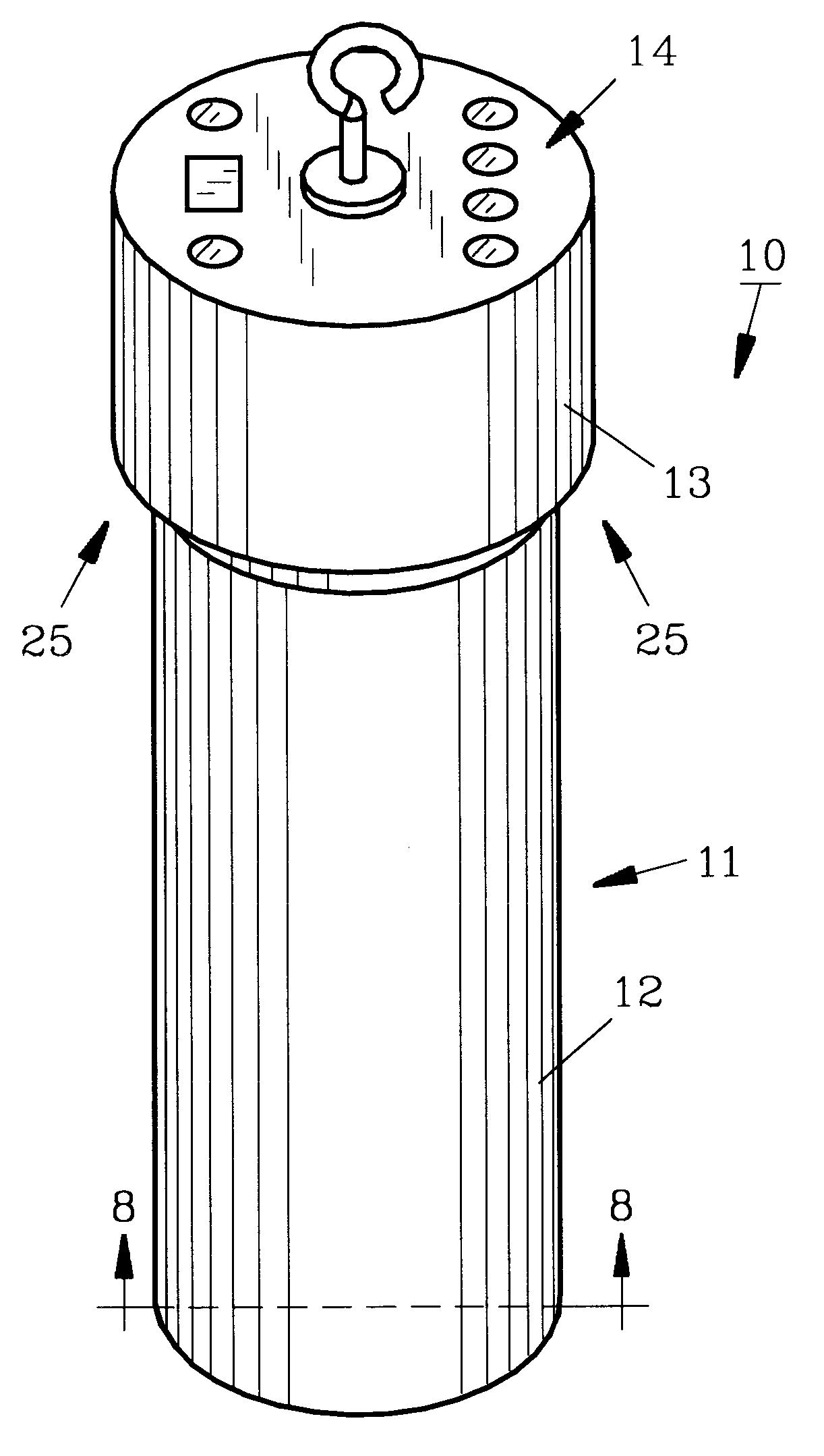
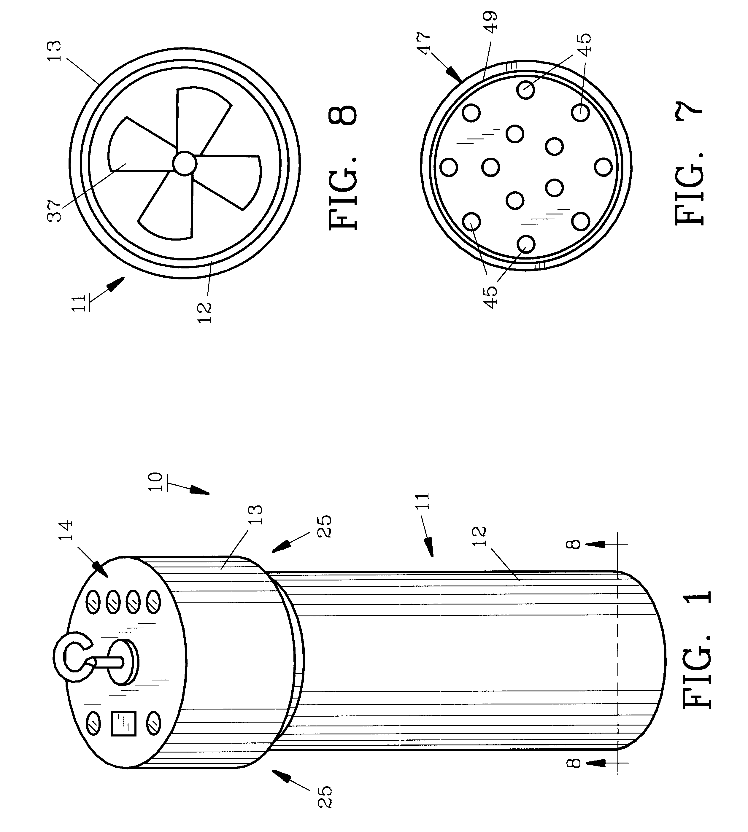
For a better understanding of the invention and its operation, turning now to the drawings, FIG. 1 demonstrates preferred scent dispenser 10 for luring game which includes cylindrical housing 11 with a smaller diameter lower cylinder or body 12 joined to upper cylinder or cap 13 which has a somewhat larger diameter. Cylinders 12 and 13 are each formed from suitable, durable, rigid polymeric materials preferably by conventional molding or extruding. Body 12 is preferably approximately 4.75 cm in width and 14.5 cm in length, whereas cylinder 13 is preferably approximately 5.5 cm in width and 4 cm in length for convenience in carrying and storing. Body 12 includes a pair of opposing reversed L-shaped slots 60, 60' (60' not seen) in FIG. 3 which receive cap posts 61, 61' respectively. Cap 13 can be easily, rotatably removed from body 12 for supplying fresh batteries 30 as needed. Housing 11 provides an air channel 25 for entry of fresh air which is drawn between body 12 and cap 13 by fa...


PUM

PropertyMeasurementUnit
widthaaaaaaaaaa
widthaaaaaaaaaa
widthaaaaaaaaaa

Abstract

A portable, convenient scent dispenser and method of operation allows the user to quickly change scents used therein as desired while hunting. A scent receptacle mounted in the lower end of a cylindrical housing is removable for replacing or exchanging scented materials. The scent dispenser provides a cylindrically-shaped housing having a removable cap containing microcontrolled electrical circuitry which includes mode indicators and a select switch. The lower body of the housing contains a battery assembly and an electric fan. The scent dispenser can be manually, selectively operated in a variety of modes to allow the fan to run continuously, cyclically, or cyclically only during daylight hours for economical power consumption.

Description

The invention herein pertains to a scent dispenser for luring deer or the like and in particular pertains to a scent dispenser which utilizes microcontroller circuitry for selective operation of a fan which forces air past a contained, conventional scent-producing material for scent distribution into the surrounding atmosphere.DESCRIPTION OF THE PRIOR ART AND OBJECTIVES OF THE INVENTIONVarious mechanical and electrical scent-dispensing devices have been used in the past by hunters, photographers and others to attract deer and other game. These devices are generally suspended from tree limbs or are otherwise advantageously positioned for the best results. Certain of the prior art devices are large and bulky, requiring special care during handling and transportation. Other electrical prior art devices must be turned on manually while hunting and thereafter turned off to terminate power consumption to prevent battery depletion. Other known prior art devices are mechanical in nature and...

Claims


Application Information

Patent Timeline
Patent Type & Authority Patents(United States)
IPC IPC(8): A01M1/20A01M31/00A61L9/12
CPCA01M1/2033A01M1/2044A01M1/2055A01M31/008A61L9/122Y10S261/88
Inventor COX, LARRY R.
Owner ENE HUNTING PROD
Why Eureka
Try Eureka