Resistor assembly and cathode ray tube

a technology of resistors and tubes, applied in the field of resistors, can solve problems such as saving time in the manufacturing process

Inactive Publication Date: 2003-07-15
KONINKLIJKE PHILIPS ELECTRONICS NV
View PDF5 Cites 7 Cited by
  • Summary
  • Abstract
  • Description
  • Claims
  • Application Information

AI Technical Summary

Problems solved by technology

Furthermore, the predetermined value of the additional resistive network can be obtained by fewer releasing steps of the bridge connections, which saves time in the manufacturing process.

Method used


Image

  • Resistor assembly and cathode ray tube
  • Resistor assembly and cathode ray tube
  • Resistor assembly and cathode ray tube

Examples


Embodiment Construction

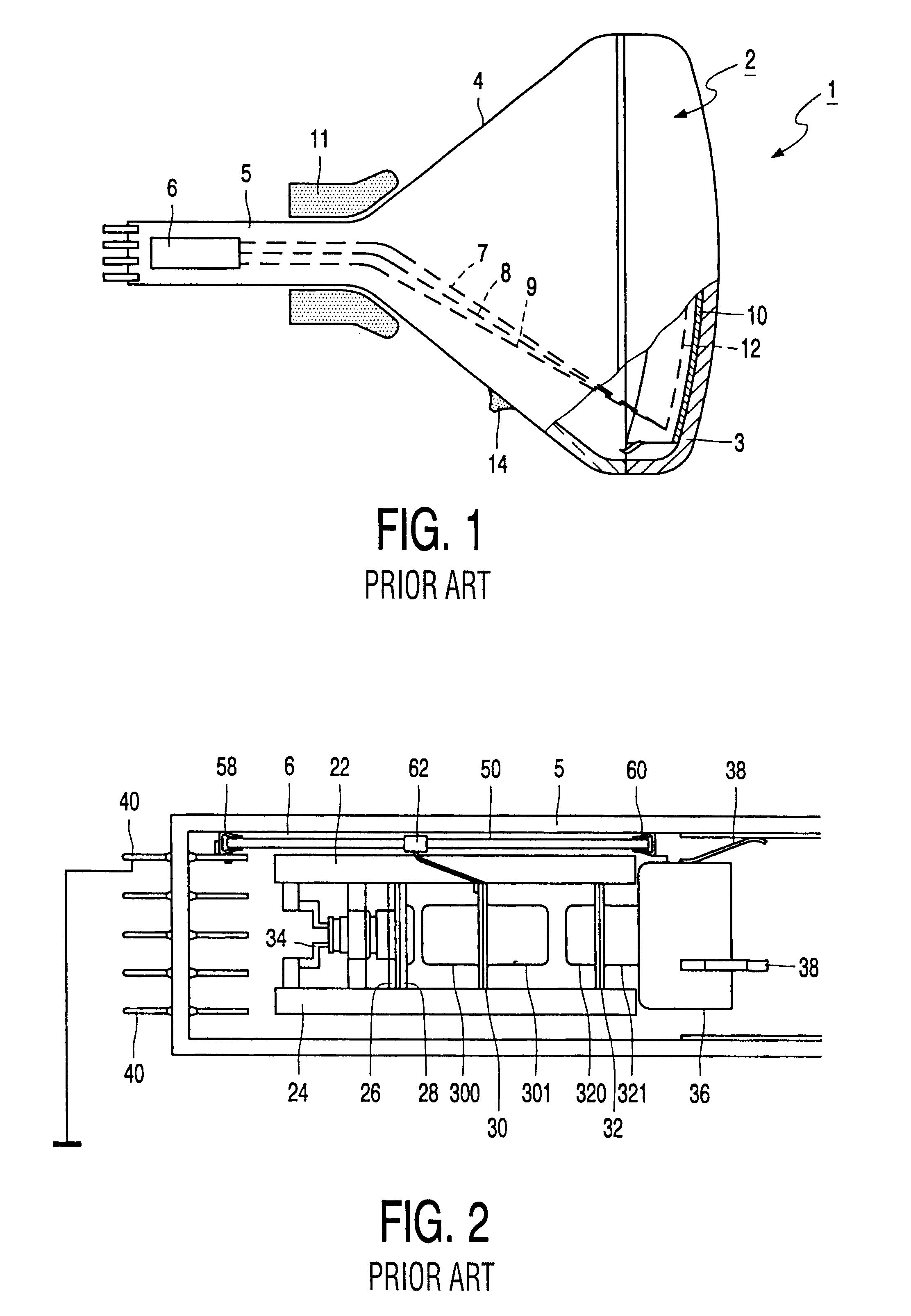
The cathode ray tube 1 shown in FIG. 1 comprises an evacuated glass envelope 2 with a neck 5, a funnel-shaped part 4 and a front panel 3, which may be either curved or flat. A display screen 10 having a pattern of, for example, lines or dots of phosphors luminescing in different colors (e.g. red, green and blue) may be arranged on the inner side of the panel 3. A thin mask 12 supported by a frame is positioned at a small distance from the display screen 10. The mask 12 may be an apertured mask having circular or elongate apertures, or a wire mask. During operation of the tube, an electron gun system 6 arranged in the tube neck 5 sends electron beams 7, 8, 9 through the mask 12 to the display screen 10 so that the phosphors will emit light. The electron beams have a small mutual angle causing, at the proper mask-to-screen distance, the electron beams to only impinge on the phosphors of the associated color. A deflection device 11 ensures that the electron beams systematically scan th...


PUM


Abstract

The invention relates to a resistor assembly for dividing an applied voltage into an intermediate voltage being below the applied anode voltage in a cathode ray tube. The resistor assembly comprises an insulating substrate and a resistive voltage divider including a first and a second resistive layer provided on the insulating substrate, and an additional resistive network with a first network terminal and a second network terminal. The additional resistive network is coupled in series with the first resistive layer. Furthermore, the additional resistive network comprises first and second resistive portions which are releasably coupled to the network terminals via bridge connections. According to the invention, the first and second resistive portions have substantially different resistance values for selecting a predetermined resistance value from a range of resistance values of the additional resistive network.

Description

1. Field of the InventionThe invention relates to a resistor for dividing an applied voltage into an intermediate voltage being below the applied voltage. The invention further relates to a cathode ray tube and an electrode gun.2. Description of the Related ArtSuch a resistor assembly is known from European patent application EP-A-36901. The resistor assembly described in this document is used in electron guns for cathode ray tubes (CRT). The known resistor assembly is mounted on the electron gun in the neck of the CRT. A first terminal of the resistor assembly is connected to a stem pin of the electron gun of the cathode ray tube, a second terminal of the resistor assembly is coupled to the anode of the cathode ray tube and a third terminal of the resistor assembly is connected to an intermediate grid of the electron gun of the cathode ray tube. The resistor assembly is used for supplying the intermediate voltage to the intermediate grid. This intermediate voltage is divided by the...

Claims


Application Information

Patent Timeline
Patent Type & Authority Patents(United States)
IPC IPC(8): H01J29/00H01J29/96H01J29/48
CPCH01J29/96H01J2229/966H01J29/48
Inventor AARNINK, WILHELMUS ALBERTUS MARIACOMPTER, JOHAN CORNELIS
Owner KONINKLIJKE PHILIPS ELECTRONICS NV
Why Eureka
Try Eureka