Electronic device
a technology of electronic devices and panel displays, applied in the field of electronic devices, can solve the problems of complex control operations, uninteresting display during changes in functional mode display, and the configuration cannot flexibly meet the needs of the present-day information-oriented society, and achieve the effect of simple display control and effective use of panel displays
- Summary
- Abstract
- Description
- Claims
- Application Information
AI Technical Summary
Benefits of technology
Problems solved by technology
Method used
Image
Examples
first embodiment
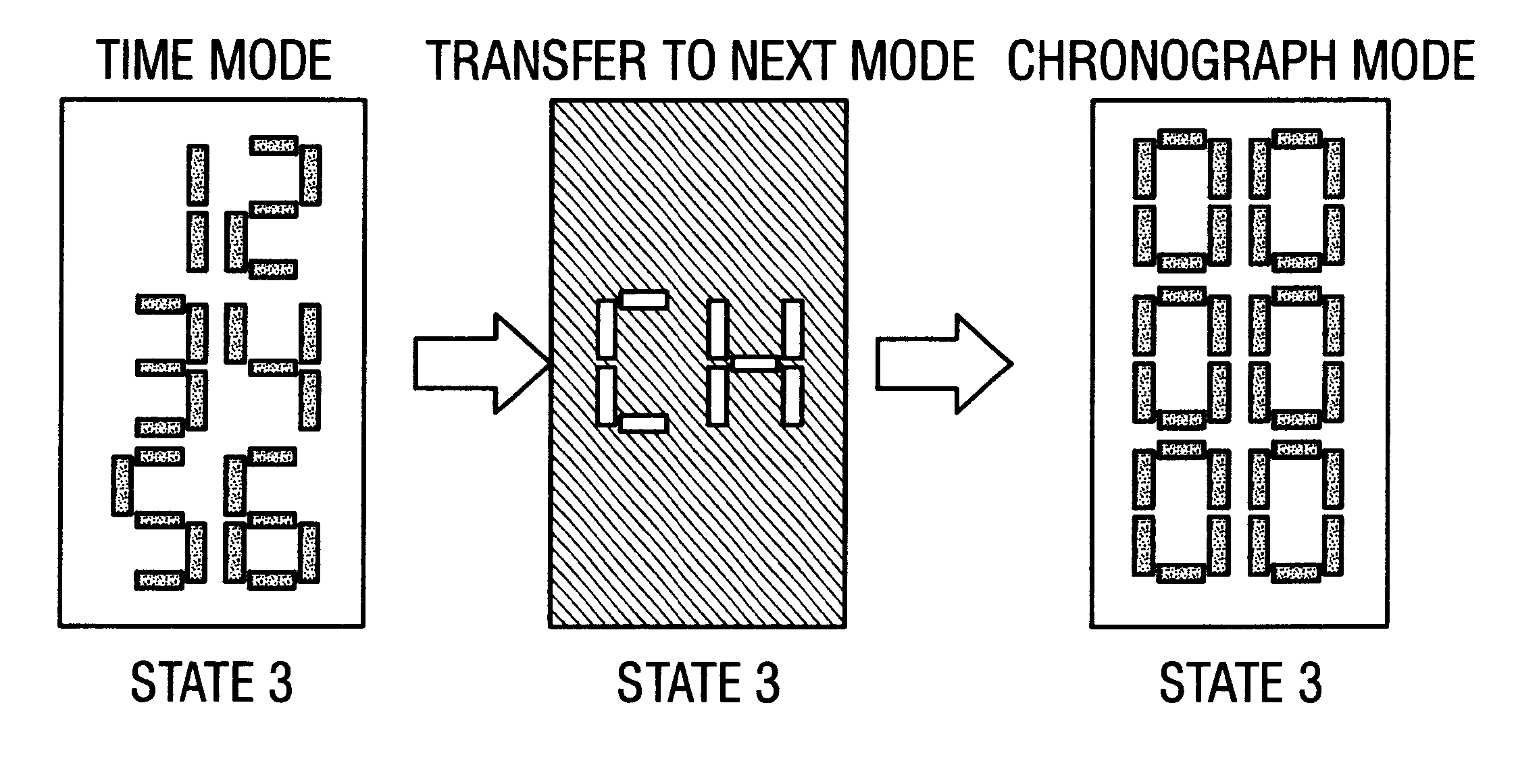
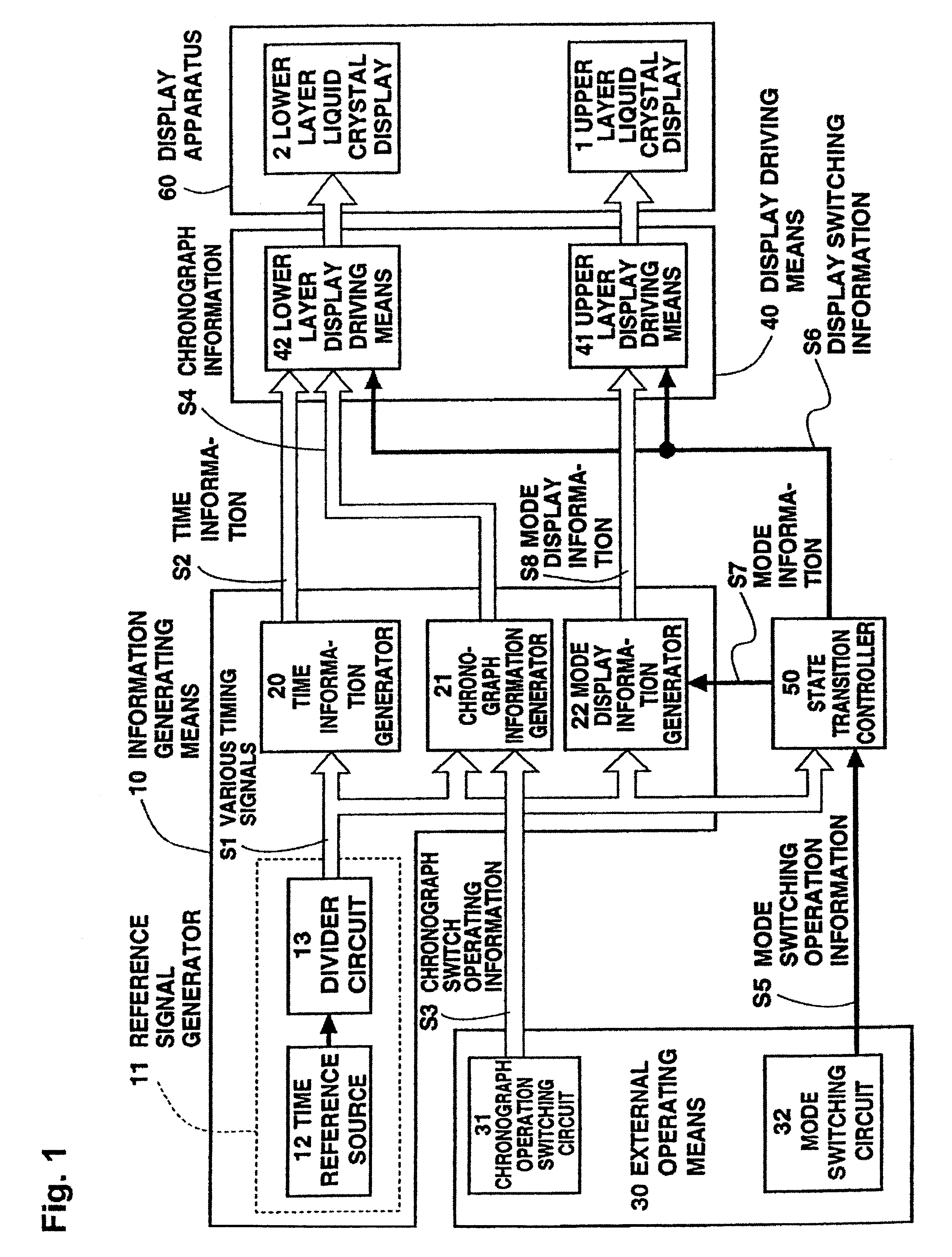
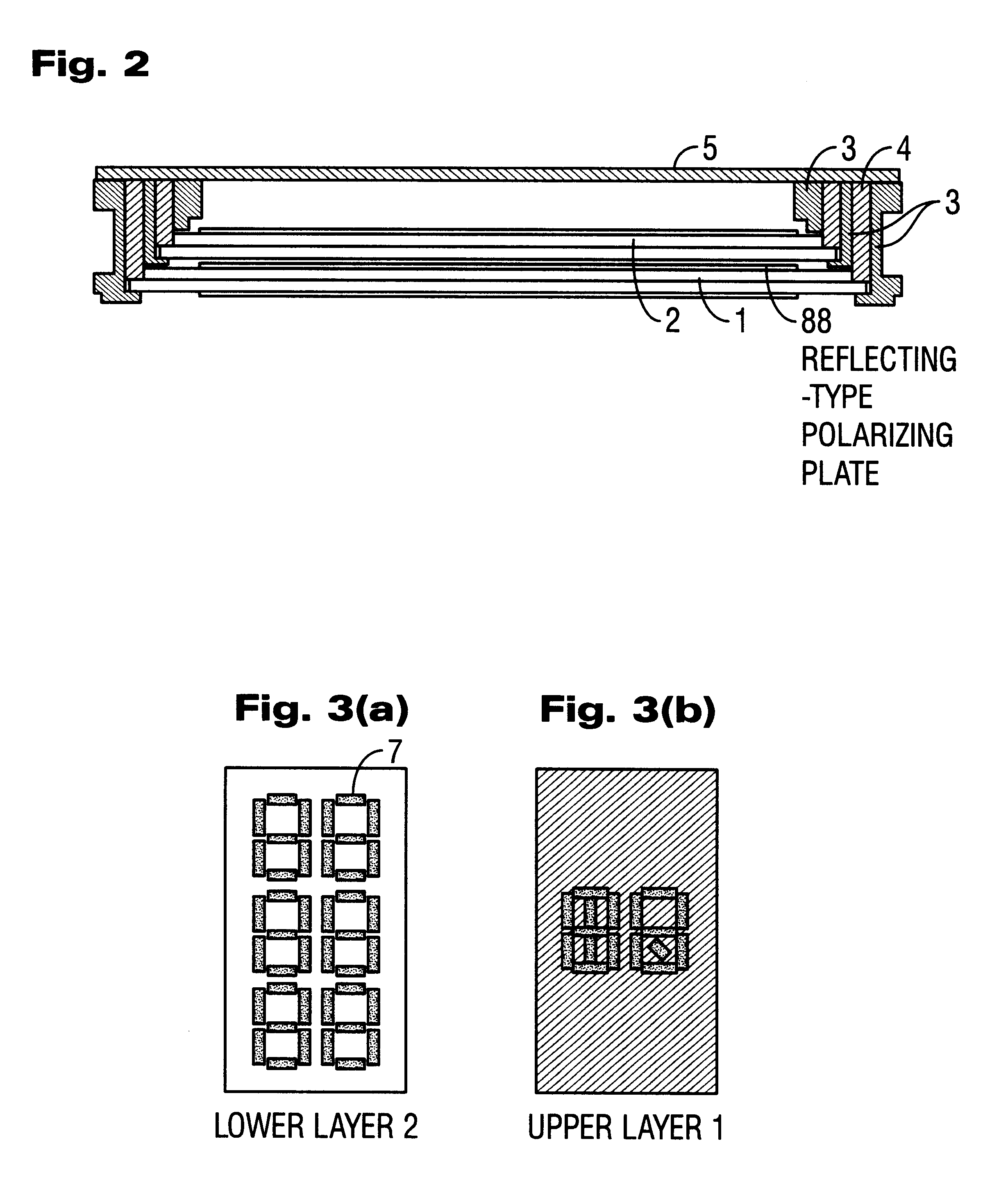
Embodiments of the present invention will be described hereinafter with reference to the attached drawings. FIG. 1 is a block diagram of an upper and lower two-layer liquid crystal display apparatus, which is the present invention. The system configuration of this embodiment comprises information generating means 10, external operating means 30, display driving means 40, a state transition controller 50, and a display apparatus formed from an upper layer liquid crystal display 1 and a lower layer liquid crystal display 2.
The external operating means 30 comprises a chronograph operation switching circuit 31 and a mode switching circuit 32, each respectively outputting chronograph switch operating information 53 and mode switching operation information S5. The display driving means 40 comprises upper layer display driving means 41 for driving the upper layer liquid crystal display 1 and lower layer display driving means 42 for driving the lower layer liquid crystal display 2.
The infor...
second embodiment
FIGS. 5 (a)-5(e) give transition diagrams showing the display transitions in the second embodiment according to the present invention. This embodiment has a mirror display state that does not belong to either the time mode or chronograph mode. All mode transitions are performed via the mirror display state. The transition diagrams of FIGS. 5(a)-5(e) show a case where the mirror display state transfers to the time mode and thereafter again transfers back to the mirror display state.
Hereinafter, the transition diagrams showing the display transitions of the second embodiment according to the present invention of FIGS. 5(a)-5(e) will be described with reference to Table 1.
First is the mirror display state of state 1 (FIG. 5 (a)). In this state, the upper layer liquid crystal display 1 is in the mirror state and the user does not obtain information. However, state 1 is highly effective since there is a power saving effect due to the all OFF state, and moreover the mirror display itself ...
third embodiment
Next, the multifunction digital electronic watch of a third embodiment according to the present invention will be described with reference to FIGS. 8, 9(a),9(b), 10(a) and 10(b). FIG. 8 is a circuit block diagram, FIGS. 9(a) and 9(b) are respectively top views of segments of the upper layer and lower layer liquid crystal display panels, FIGS. 10 (a) and 10(b) are respectively top views showing the information display states on the upper layer and lower layer liquid crystal display panels. First, the circuit block diagram of FIG. 1 will be described. In FIG. 8, an oscillator circuit 111 supplies a 32768 Hz signal to a divider circuit 112, the divider circuit 112 is formed from a plurality of stages of dividers and supplies a divided signal group to information generating means 102, the information generating means 102 supplies predetermined information to display driving means 103 under control of various control signals from external operating means 105 and mode controlling means 10...
PUM
 Abstract
Description
Claims
Application Information
 - R&D
- Intellectual Property
- Life Sciences
- Materials
- Tech Scout
- Unparalleled Data Quality
- Higher Quality Content
- 60% Fewer Hallucinations
Browse by: Latest US Patents, China's latest patents, Technical Efficacy Thesaurus, Application Domain, Technology Topic, Popular Technical Reports.
© 2025 PatSnap. All rights reserved.Legal|Privacy policy|Modern Slavery Act Transparency Statement|Sitemap|About US| Contact US: help@patsnap.com


