Limited slip differential

Inactive Publication Date: 2003-07-29
ILLINOIS TOOL WORKS INC
View PDF8 Cites 17 Cited by
  • Summary
  • Abstract
  • Description
  • Claims
  • Application Information

AI Technical Summary

Benefits of technology

is to provide novel limited slip differentials that are economical.
A further object of the invention is to provide novel limited slip differentials having improved reliability.
Still another object of the invention is to provide novel limited slip differentials that produce less noise.
Yet another object of the invention is to provide novel limited slip differentials having improved performance.

Problems solved by technology

Friction between the planetary gears and the carrier bores limits the slip of the differential.

Method used


Image

  • Limited slip differential
  • Limited slip differential
  • Limited slip differential

Examples


Embodiment Construction

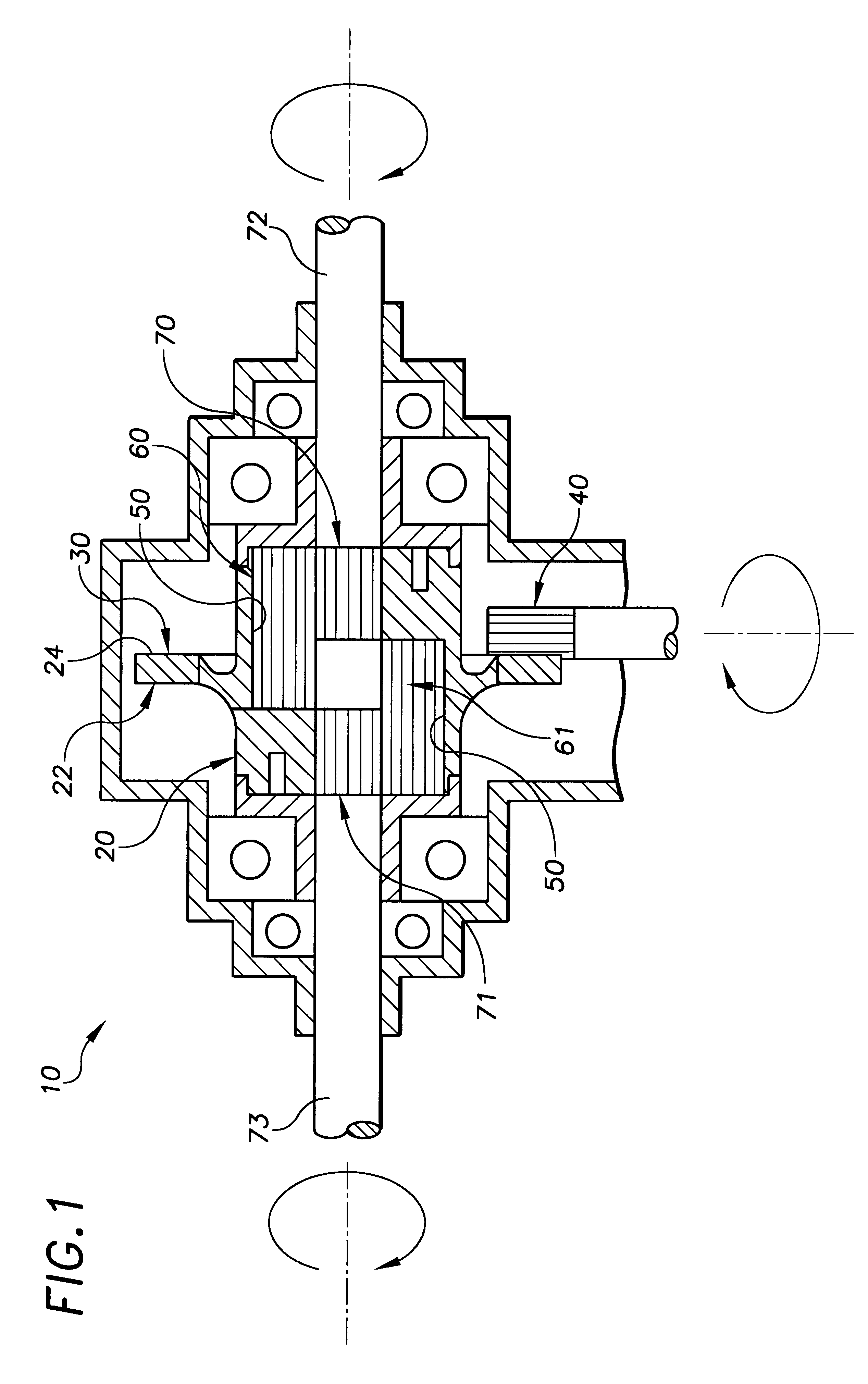
FIG. 1 illustrates a limited slip differential 10 generally comprising a carrier 20 having a radial flange 22 disposed about a rotation axis thereof.

The radial flange 22 generally comprises a skew axis geared surface thereon for engagement with a pinion coupled to an output of a motor or other rotary drive member.

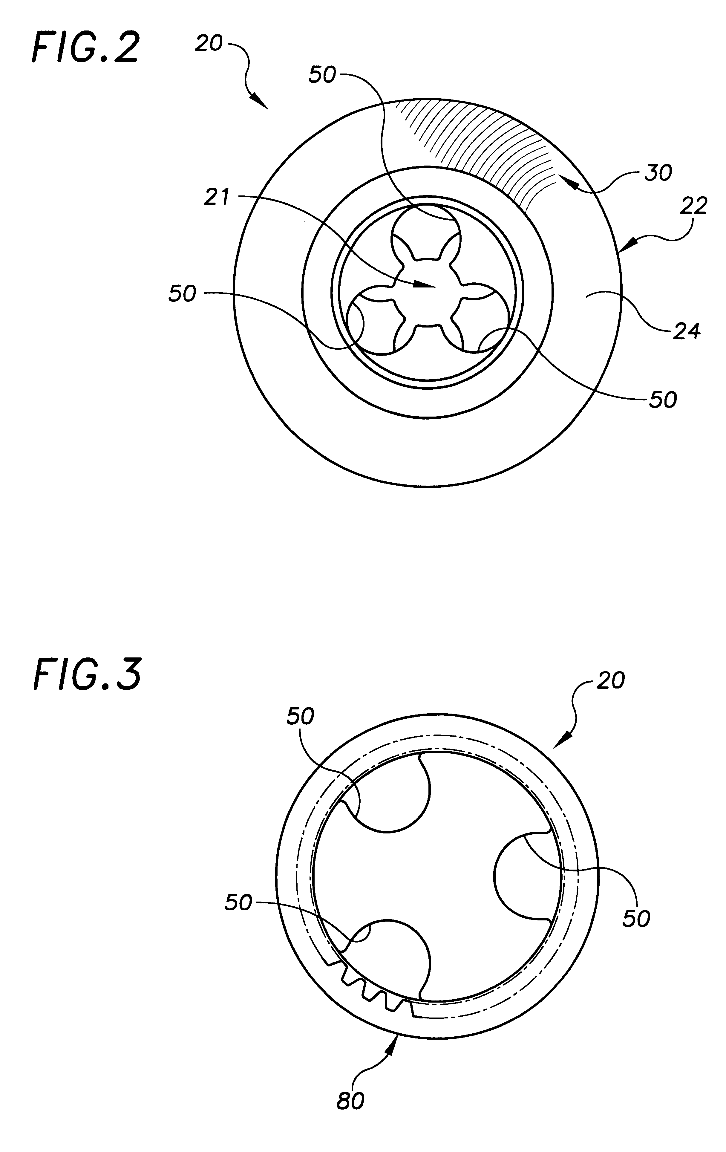
In the exemplary embodiment of FIGS. 1 and 2, the skew axis geared surface is a gear face 30 disposed on a first side 24 of the radial flange 22 about the rotation axis. The exemplary pinion 40 and face gear 30 preferably comprise teeth having different pressure angles, for example HELICON or SPIROID gear forms by ITW Spiroid, Glenview, Ill.

In alternative embodiments, the pinion and geared surface of the carrier may have other known gear configurations, for example a bevel or worm gear form, or a HYPOID gear form.

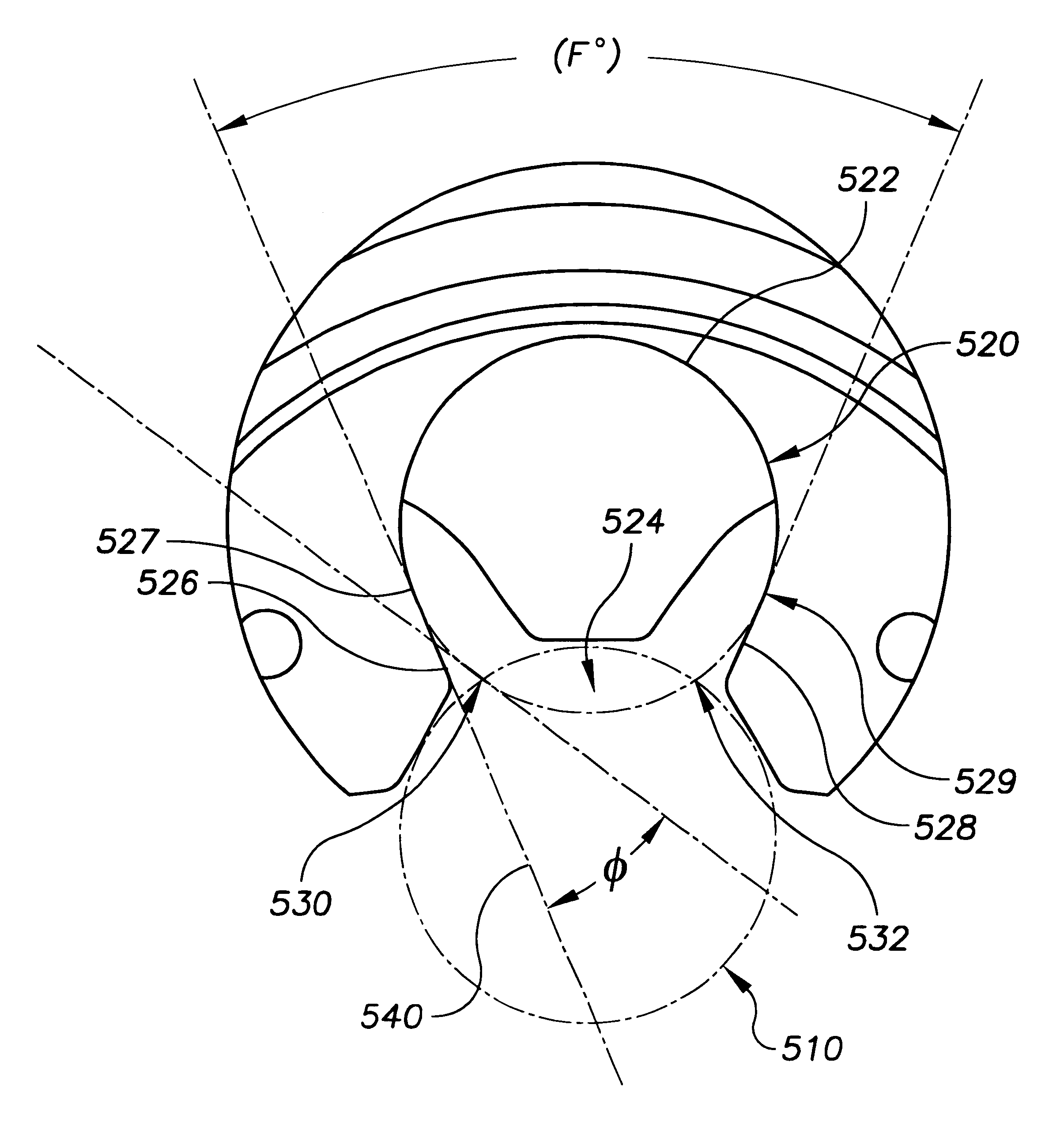
The carrier also generally comprises a first plurality of open-sided recesses disposed symmetrically about the carrier rotation axis on a first side thereof, and a...


PUM


Abstract

A limited slip differential having a carrier with a plurality of recesses disposed symmetrically relative to a gear opening. The gear opening having a gear diameter, and each of the plurality of recesses having a recess diameter. The gear diameter intersecting the recess diameter of each of the plurality of recesses at corresponding first and second intersections, an acute angle between a line tangent to the recess diameter at the first intersection and a tangent line of the recess diameter along which first and second chamfers extend is between approximately 30 degrees and approximately 32 degrees.

Description

BACKGROUND OF THE INVENTIONSThe invention relates generally to differentials, and more particularly to limited slip differentials.Limited slip differentials are known generally and employed commonly in rear wheel and center differentials, among many other applications.U.S. Pat. No. 3,292,456 entitled "Spin Limiting Differential", assigned commonly herewith, for example, discloses a rotatable carrier having a plurality of open-sided bores with a corresponding plurality of planetary gears disposed symmetrically therein about a rotation axis of the carrier. A portion of each planetary gear protrudes from the open side of the corresponding bore and is coupled to a drive shaft, or axle. Friction between the planetary gears and the carrier bores limits the slip of the differential.An object of the present invention is to provide novel limited slip differentials that improve upon and overcome problems in the art.Another object of the invention is to provide novel limited slip differentials...

Claims


Application Information

Patent Timeline
Patent Type & Authority Patents(United States)
IPC IPC(8): F16H48/28F16H48/20F16H48/06F16H48/00F16H48/10F16H48/285
CPCF16H48/285F16H2048/102
Inventor CARINGELLA, ANTHONY R.GRUSZKOWSKI, JAMES A.NOWAKOWSKI, WESLEY P.
Owner ILLINOIS TOOL WORKS INC
Why Eureka
Try Eureka