
Self-propelled infrared emission aerial target

a technology of infrared emission and aerial targets, which is applied in the direction of measuring devices, scientific instruments, instruments, etc., can solve the problems of substantial damage and body injuries of the personnel in charge of launching

Inactive Publication Date: 2003-07-29
DOE PASCAL +3
View PDF11 Cites 3 Cited by
  • Summary
  • Abstract
  • Description
  • Claims
  • Application Information

AI Technical Summary

Problems solved by technology

Although it is efficient, such a target has a number of drawbacks.
Actually, if the propulsion system does not work during the launching, while the infrared radiation emitters are working, the device may be detected by a missile and destroyed while on the ground, bringing about substantial damage and body injuries for the personnel in charge of the launching.

Method used


Image

  • Self-propelled infrared emission aerial target
  • Self-propelled infrared emission aerial target
  • Self-propelled infrared emission aerial target

Examples


Embodiment Construction

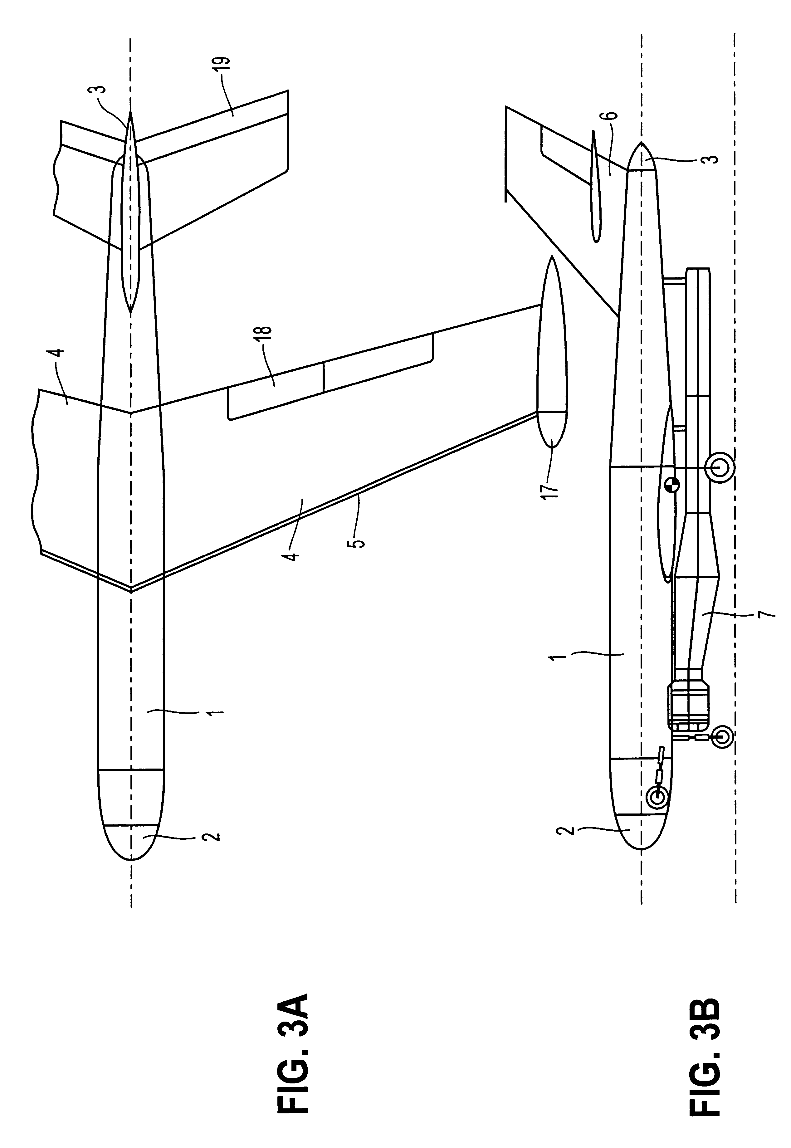
According to an embodiment of the invention, as demonstrated in FIGS. 3A-B, the self-propelled aerial target is aircraft-shaped. It has a fuselage 1 with a nose 2 and a tail 3, wings 4 with leading edges 5, and a tail assembly 6.

A propulsion system 7 is disposed under fuselage 1 and attached thereto. As demonstrated in FIG. 4, the propulsion system has an air inlet 8, a combustion chamber 9, and a nozzle 20 for discharging the combustion gases.

A fuel injector 11 located in combustion chamber 9 is connected by a supply line 12 to a fuel tank 13 located inside fuselage 1. Also, a pipe 14 that divides into three secondary pipes 14.sub.1, 14.sub.2, and 14.sub.3 connects propulsion nozzle 20 to a first chamber 15 located in the nose 2 of fuselage 1, to two other second chambers 16 each located in the leading edge 5 of one of the two wings 4, and two other chambers 17 located at the ends of the wings and forming outer elements attached to the target.

Nozzle 20 is comprised of a divergent-c...


PUM


Abstract

A self-propelled infrared emission aerial target has an aircraft- or a missile-shaped body and a nose, wings and / or control surfaces, a system for feeding fuel and oxidizer to a combustion chamber in which combustion gases are produced and for supplying the combustion gases to a propulsion nozzle, and an infrared radiation emitter. The target has at least one conduit connecting the combustion chamber or propulsion nozzle of the propulsion system to a nose, wing and / or control surface of the target, or to an outside element attached thereto.

Description

1. Field of InventionThe present invention relates to the field of moving aerial targets, in particular a self-propelled infrared emission aerial target having a body, a propulsion system, and an infrared radiation emission system.2. Description of Related ArtSelf-propelled aerial targets are used particularly within the framework of missile development testing or troop training and in the framework of decoying to escape a missile attack.Some of these missiles are of the infrared guidance type, namely they seek the target by detecting its infrared signature. Then, their control surfaces are moved to guide them on a given trajectory leading to the destruction of the target.For development of such missiles, the target described in Patent WO 9727446, which has a fuselage, propulsion systems, and infrared radiation emitters, is known. The infrared radiation emitters are comprised of a heat entity which is composed of an oil burner that heats a heat-conducting surface so that the latter ...

Claims


Application Information

Patent Timeline
IPC IPC(8): F41J9/00F41J9/08
CPCF41J9/08
Inventor DOE, PASCALGUIDETTI, HERVETHAVOT, GILLESRANTET, ERIC
Owner DOE PASCAL
Learn More