
System and method for forming a beam and creating nulls with an adaptive array antenna using antenna excision and orthogonal Eigen-weighting

a phased array and antenna technology, applied in diversity/multi-antenna systems, direction finders using radio waves, instruments, etc., can solve the problems of inability to ascertain the direction of the signal source with sufficient accuracy, introduce an unacceptable amount of error into the process, and particularly problematic with respect to spread spectrum and other signals

Inactive Publication Date: 2003-08-05
RAYTHEON CO
View PDF5 Cites 12 Cited by
  • Summary
  • Abstract
  • Description
  • Claims
  • Application Information

AI Technical Summary

Problems solved by technology

Unfortunately, in many cases it may be difficult to ascertain the direction of the signal source with sufficient accuracy.
This is particularly problematic with respect to spread spectrum and other signals having a signal strength below the noise level.
However, for many applications, an assumption with respect to the location of the signal source may introduce an unacceptable amount of error into the process.
This solution can be expensive and potentially require an IMU of considerable size and weight.
Hence, angle of arrival approaches tend to be expensive, cumbersome and prone to error.
Unfortunately, the efficacy of this approach is limited in situations where the jamming source is intermittently activated.
Unfortunately, as is well-known in the art, the capacity of an array is dictated by the number of antenna elements thereof.
Hence, in environments with many jammers, the antenna may be preoccupied with interference cancellation.
Inasmuch as many interferers may be wideband interferers, operating over a broad frequency range, this technique alone may be inadequate for many applications.

Method used


Image

  • System and method for forming a beam and creating nulls with an adaptive array antenna using antenna excision and orthogonal Eigen-weighting
  • System and method for forming a beam and creating nulls with an adaptive array antenna using antenna excision and orthogonal Eigen-weighting
  • System and method for forming a beam and creating nulls with an adaptive array antenna using antenna excision and orthogonal Eigen-weighting

Examples


Embodiment Construction

Illustrative embodiments and exemplary applications will now be described with reference to the accompanying drawings to disclose the advantageous teachings of the present invention.

While the present invention is described herein with reference to illustrative embodiments for particular applications, it should be understood that the invention is not limited thereto. Those having ordinary skill in the art and access to the teachings provided herein will recognize additional modifications, applications, and embodiments within the scope thereof and additional fields in which the present invention would be of significant utility.

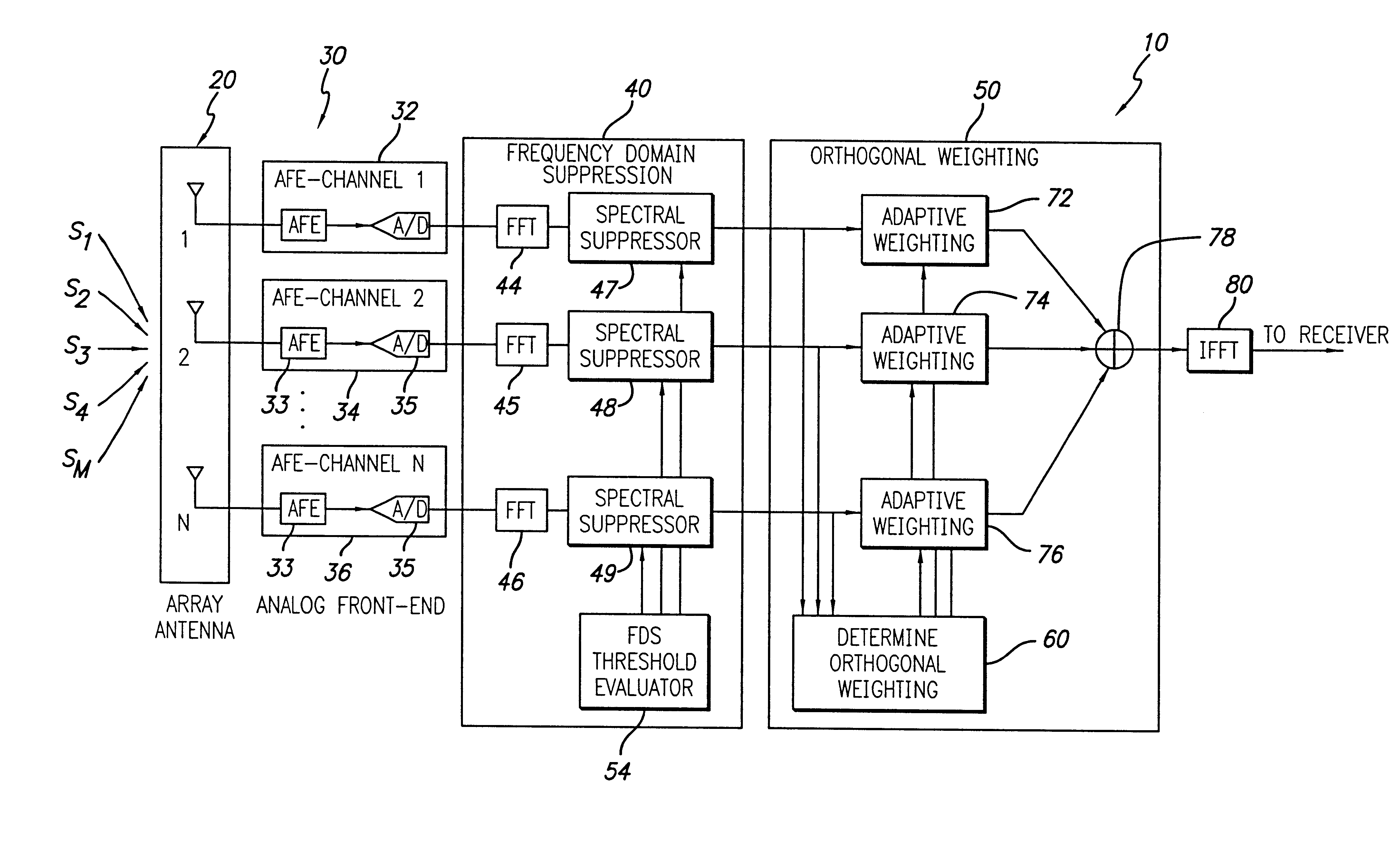
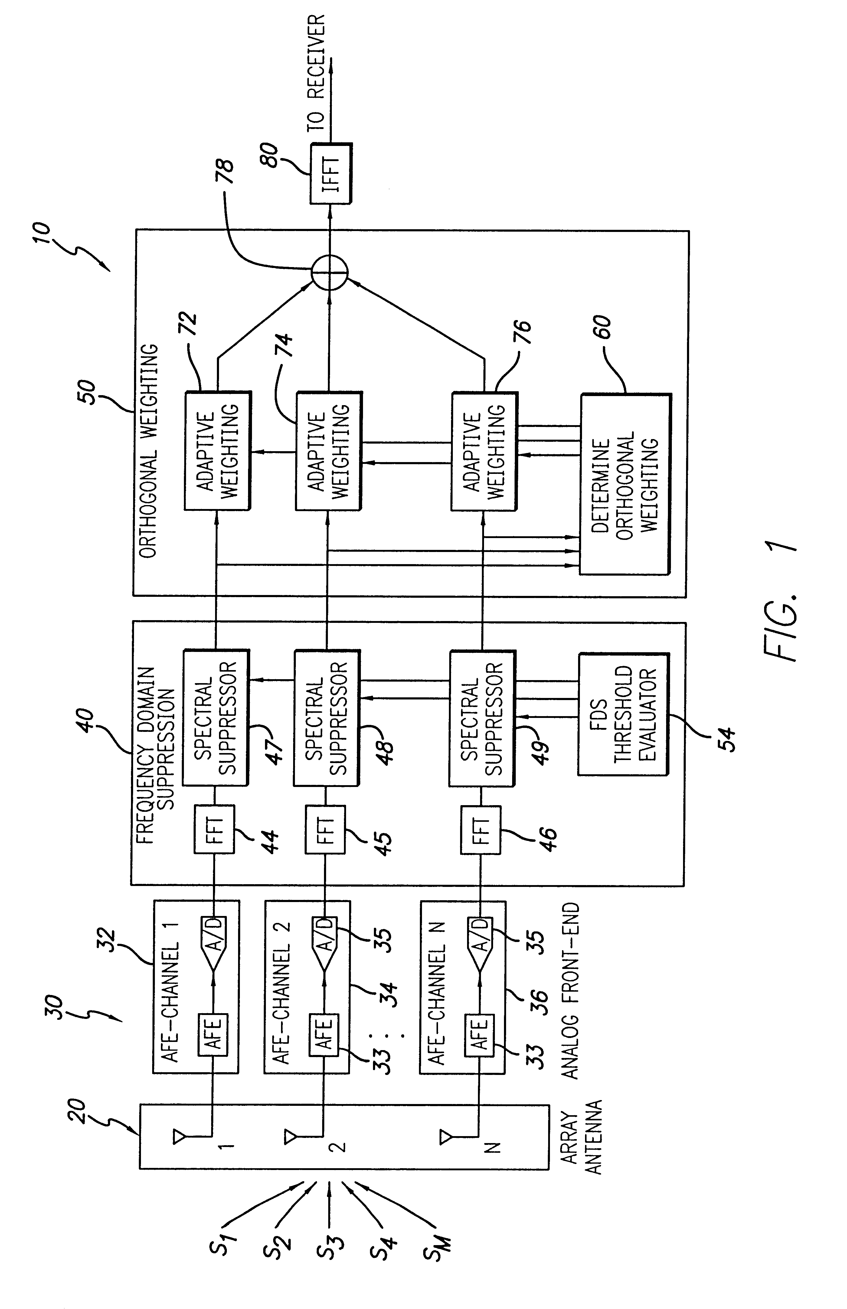
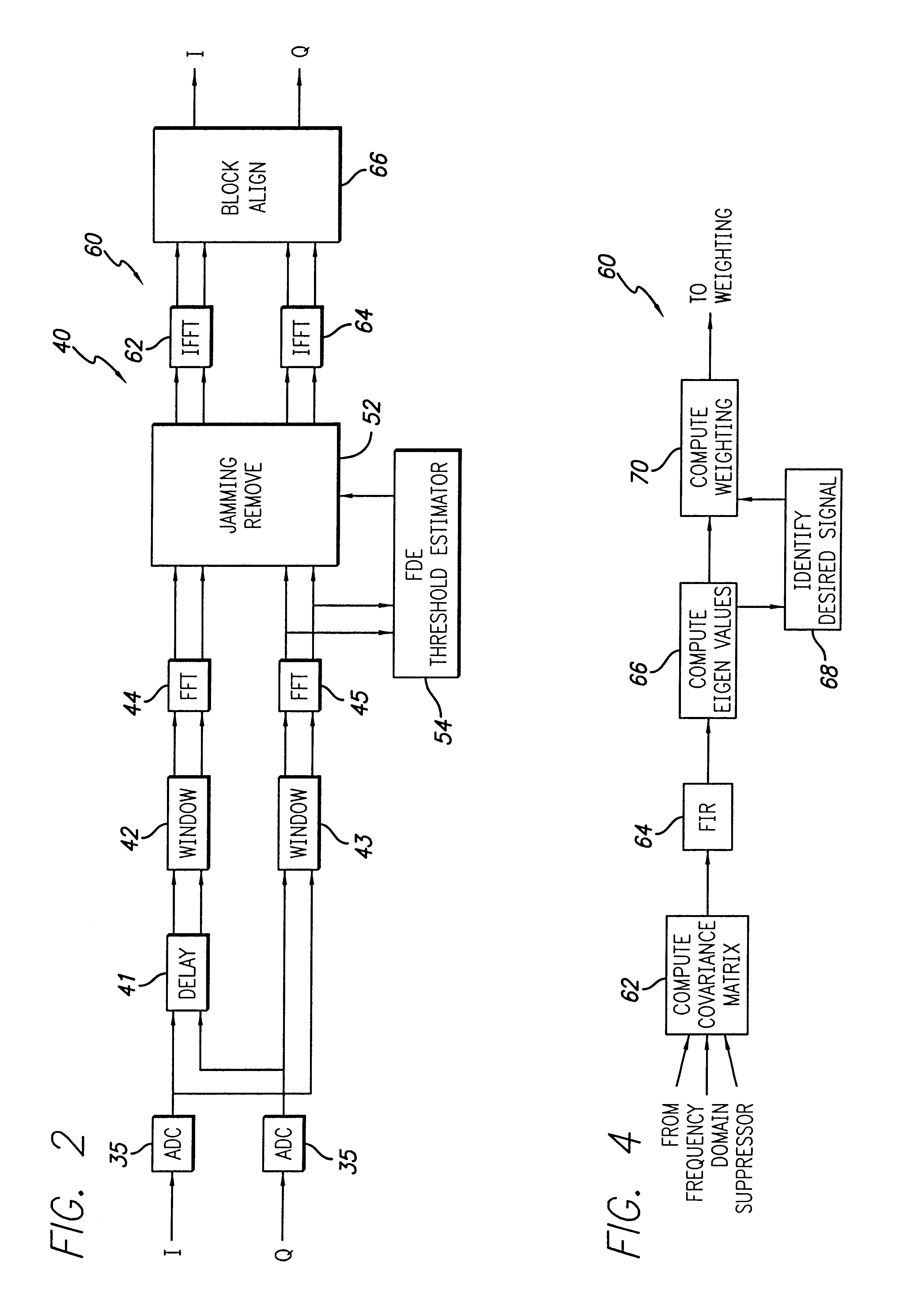
FIG. 1 is a block diagram showing an illustrative implementation of a system for forming a beam and creating nulls using antenna excision and orthogonal Eigen-weighting in accordance with the teachings of the present invention. The system 10 consists of four components: an array antenna 20, an analog front-end (AFE) 30 with N channels 32, 34, . . . 36, a frequen...


PUM


Abstract

A system and method for forming a beam and creating nulls. The inventive method combines frequency domain suppression technology for narrow-band jammer rejection with orthogonal weighting using Eigen analysis for jammer nulling and signal beam-forming for an array antenna system. The inventive system is adapted for use with an adaptive array antenna having a plurality of radiating elements. The system includes a frequency domain suppressor connected to the array antenna and an orthogonal weighting subsystem connected to the frequency domain suppressor. In the illustrative implementation, signals received by each radiating elements are processed by an analog front-end and digitized. The frequency domain suppressor includes a Fast Fourier transformer (FFT) and a frequency domain suppressor for each element in the array. The frequency domain suppressor further includes a threshold evaluator which reads the signals output by the FFT's and provides threshold controls to the spectral suppressors. The orthogonal subsystem includes an adaptive weighting unit connected to the output of each of the spectral suppressors. The orthogonal weighting subsystem further includes an orthogonal weighting estimator for determining and optimal orthogonal Eigen-weighting to be applied to each of the adaptive weighting units. The outputs of each of the adaptive weighting processors are combined and inverse Fast Fourier transformed to provide one or more output beams and or one or more nulls in an efficient manner designed to leave the system with at least one degree of freedom for other functions.

Description

1. Field of the InventionThe present invention relates to antennas. More specifically, the present invention relates to system and methods for forming beams and creating nulls using phased array antennas.2. Description of the Related ArtAdaptive antenna systems have been developed to perform beam forming or spatial nulling. With knowledge of the direction of the signal source, conventional antenna beam forming techniques endeavor to maximize the signal to noise ratio with respect to signals sent to or received from desired sources and attempt to steer nulls in the direction of undesirable sources.Unfortunately, in many cases it may be difficult to ascertain the direction of the signal source with sufficient accuracy. This is particularly problematic with respect to spread spectrum and other signals having a signal strength below the noise level.Conventional beam forming techniques require knowledge of the direction of the signal sources and a method to track the angle of arrival of ...

Claims


Application Information

Patent Timeline
Patent Type & Authority Patents(United States)
IPC IPC(8): G01S3/04G01S3/42G01S3/02G01S3/14H01Q3/26G01S3/38H04B7/08
CPCG01S3/043G01S3/42H01Q3/2611G01S3/38H04B7/0845
Inventor CAI, KHIEM V.HARTMAN, ROBERT L.
Owner RAYTHEON CO
Learn More