
Re-synchronization method for a communication device

a communication device and resynchronization technology, applied in the direction of synchronisation arrangement, synchronisation signal speed/phase control, wireless communication, etc., can solve the problem of time and power consumption in the three-step process, and achieve the effect of simple and robust method

Inactive Publication Date: 2003-08-05
TESSERA ADVANCED TECH
View PDF6 Cites 23 Cited by
  • Summary
  • Abstract
  • Description
  • Claims
  • Application Information

AI Technical Summary

Benefits of technology

to provide a fast re-synchronization method, with a minimum number of steps and with minimum power consumption.
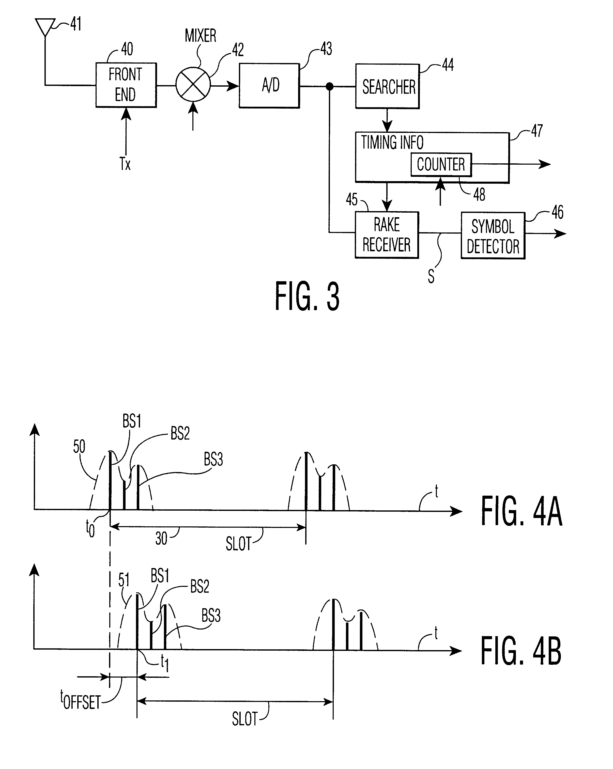
The invention is based on the insight that multi-path transmission patterns that are characteristic in time for a particular configuration of radio base stations do not change over a relatively short period of time such as a period between transmission of multiple time slots, and thus can be used to derive a timing offset for re-synchronization of the communication device after it wakes up from a sleep mode.
Advantageously, the channel profiles are fitted using a mean-square error fitting method, more particularly a mean-square error method fitting replica of said second channel profile to said first channel profile, said replica being time shifted versions of said second channel profile as time shifted over a fraction of a reception time slot of said cellular communication system. Herewith, the timing offset signal is obtained by a simple and robust method.

Problems solved by technology

Such three-step process is a time and power consuming process.

Method used


Image

  • Re-synchronization method for a communication device
  • Re-synchronization method for a communication device
  • Re-synchronization method for a communication device

Examples


Embodiment Construction

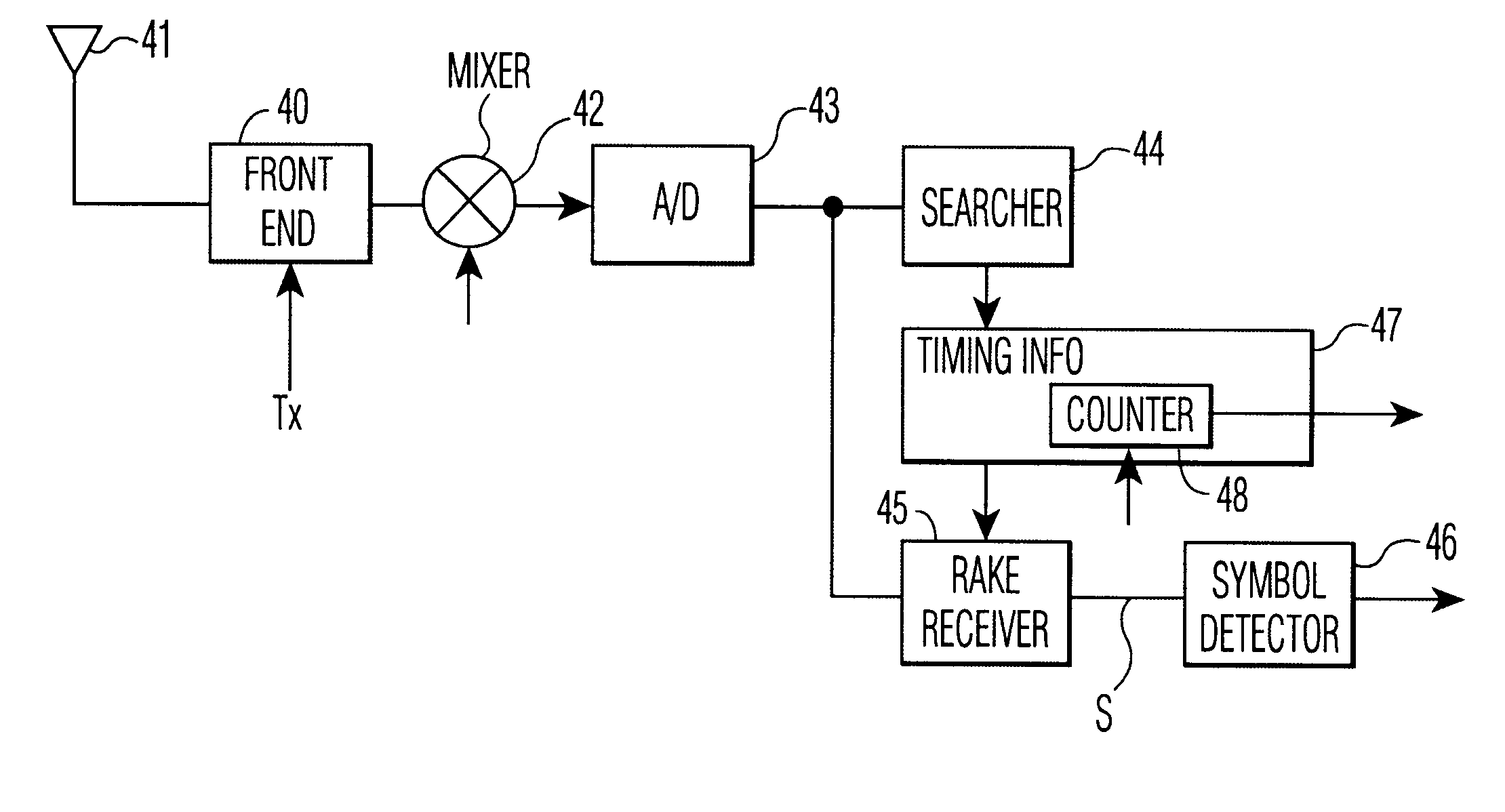
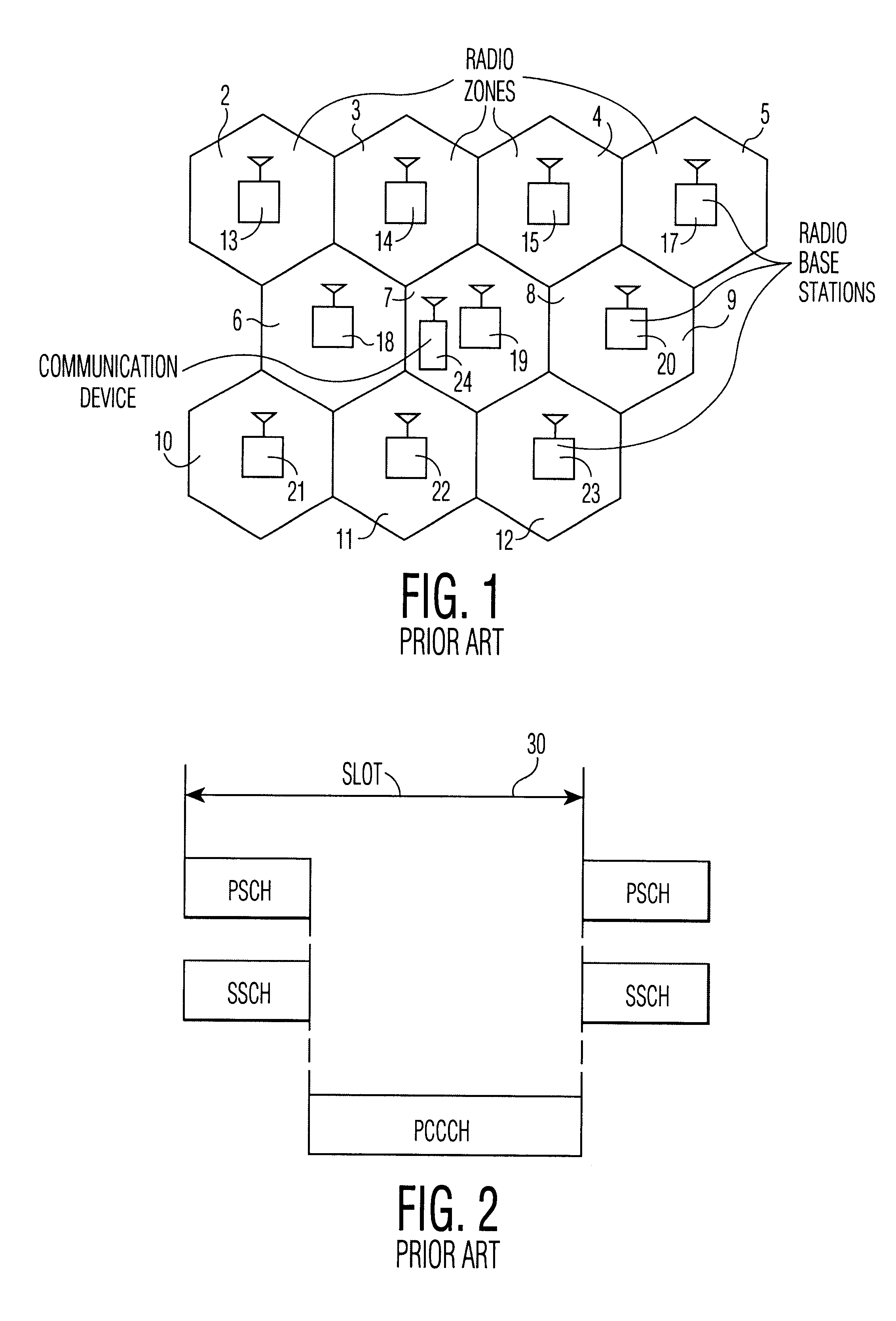
FIG. 1 schematically shows a cellular communication system 1 according to the invention. The system 1 comprises radio zones 1 to 12, each respectively comprising radio base stations 13-23. A communication device 24 is comprised in the radio zone 7. The device 24 may be a cell phone or handset, or any other suitable communication device. In the example given, the system is a direct sequence spread spectrum system with a slot based transmission scheme. Groups of radio base stations are coupled to switching centers (not shown), and the switching centers are coupled to each other. Such a cellular communication system, which may be a 3GPP system for instance, is well known in the art.

FIG. 2 shows a prior art synchronization channel configuration that is used by the system 1. The shown configuration is described in said 3GPP ETSI Publication. Shown is a primary common control channel PCCCH that is used by the radio base stations 13-23 to broadcast data to communication devices in the syst...


PUM


Abstract

A cellular communication system has a number of cells covered by radio base stations communicating with communication device. The communication devices have a master timer for internally timing the communication devices relative to a timing of the cellular communication system. The master timer of a communication device is initially synchronized to a timing reference of a radio base station that provides the currently best communication link. Upon initial synchronization, the communication device determines and stores a first channel profile of received multi-path signals relative to the initial synchronization, and then enters a sleep mode. In the sleep mode a timing reference that controls the master timer is switched off. From the sleep mode, the communication device enters a receive mode and switches on its timing reference. The communication device then determines a second channel profile of received multi-path signals, and derives a timing offset signal from a best fit obtained by fitting the first channel profile to the second channel profile. Finally, the communication device re-synchronizes the master timer on the basis of the derived timing offset signal. The first and second channel profiles are characteristic in time to a particular configuration of radio base stations.

Description

1. Field of The InventionThe present invention relates to a method of re-synchronizing a communication device comprised in a cellular communication system, more particularly to such re-synchronization when the communication device wakes up from a sleep mode after initial synchronization to a radio base station comprised in the cellular communication system.2. Description of The Related ArtCellular mobile radio or communication systems are well-known. Such cellular mobile radio systems comprise cells or radio zones, together covering a given geographical area. The cells include radio base stations that, through control and communication channels, establish and maintain communication links with mobile radio devices that are comprised in the mobile radio system, and communicate with the mobile radio devices through established communication links.One type of a cellular communication system is a Universal Mobile Telecommunication System (UMTS) spread spectrum system proposed by the 3.su...

Claims


Application Information

Patent Timeline
IPC IPC(8): H04B7/26H04L7/10
CPCH04W56/008H04W92/10H04L7/00
Inventor HIRSCH, OLAF JOSEF
Owner TESSERA ADVANCED TECH
Learn More