Device for fixing a tubular element in an inaccessible cavity

a tubular element and cavity technology, applied in the direction of cable installation in underground tubes, rod connection, instruments, etc., to achieve the effect of quick and simple installation and inexpensive installation

Inactive Publication Date: 2003-08-12
ALCATEL LUCENT SAS
View PDF8 Cites 22 Cited by
  • Summary
  • Abstract
  • Description
  • Claims
  • Application Information

AI Technical Summary

Benefits of technology

An object of the present invention is to overcome the drawbacks of the prior art by providing a fixing device for fixing a tubular element into a cavity that is inaccessible to an operator, which device is quick and simple to install, and therefore inexpensive to install. In particular, the invention provides a device which can be installed without requiring the use of a robot or of major external infrastructure.
In a preferred embodiment, said membrane covers said hoops. Thus, the hoops are protected from attack from the surroundings, and in particular from corrosion. For example, the device may be manufactured by extrusion, casting, molding, or assembling together two thicknesses of membrane on either side of the hoops.
The tubular element may be a cable, and in particular an optical fiber cable used for telecommunications, or else a hollow tube serving to receive one or more cables. In which case, the tube may be smooth or corrugated. A corrugated tube offers the advantage of being more flexible than a smooth tube, and of avoiding its wall being kinked into the inside of the tube during bending. The tube is made of a material selected from metal, in particular steel, a plastics material, glass fibers, carbon fibers, an elastomer, and a composite material.
The present invention offers the advantage that this device can be used in all types of cavity, in particular a cavity that is inaccessible to an operator, and even a cavity of very small diameter, provided that the device does not obstruct the cavity, because it is not necessary to insert an instrument into the cavity in order to put the device in place. The device of the invention is therefore easier and less costly to install.
The device may be used in all types of cavity, regardless of their diameters and regardless of the materials of which the walls are made (cement, PVC, cast iron, etc., . . . ), even when various different diameters or a plurality of materials are encountered successively along the same duct. In addition, it is not necessary to position it over the entire length of a tubular cavity, but rather it is necessary merely to equip the linear portions of said cavity with said device. Once the device has been installed, a surface that is very clean and smooth is available in advantageous manner over the angular portion of the wall corresponding to the length of the deployed hoop.

Problems solved by technology

The presence of the membrane secures the hoops together and makes it unnecessary to use a tool for installing the device in the cavity.

Method used


Image

  • Device for fixing a tubular element in an inaccessible cavity
  • Device for fixing a tubular element in an inaccessible cavity
  • Device for fixing a tubular element in an inaccessible cavity

Examples


Embodiment Construction

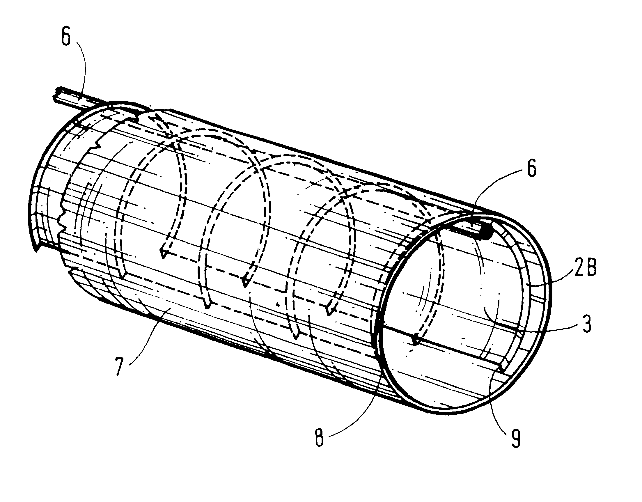
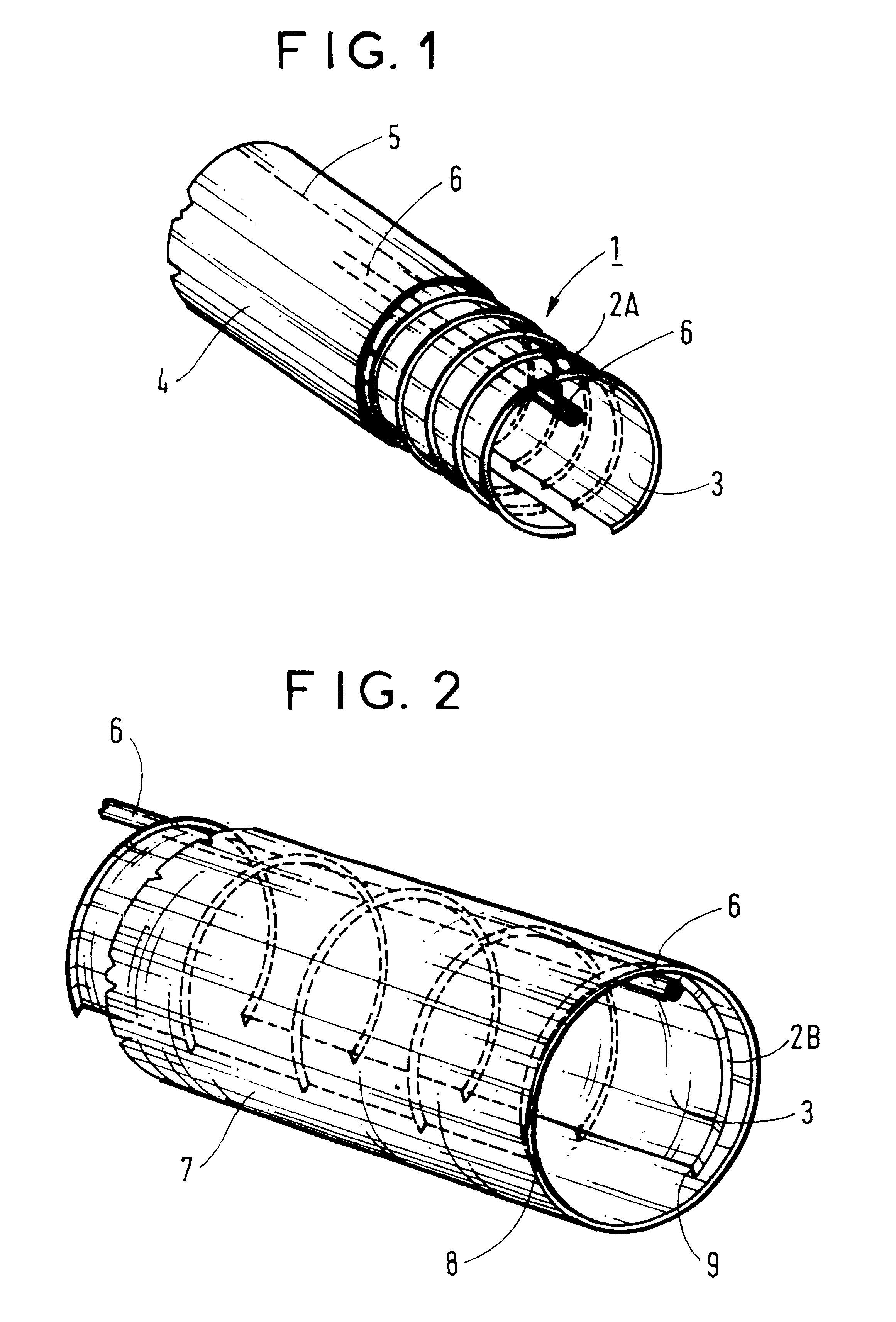
FIG. 1 shows a device 1 of the present invention, made up of hoops 2A in a contracted configuration, and interconnected by a membrane 3. The hoops 2A are metal strips made of spring steel and whose thickness is less than their width. For example their thickness lies in the range 1 mm to 5 mm and their width lies in the range 2 mm to 50 mm. The hoops 2A are held in this position by a sheath 4, e.g. made of a plastics material, and shown in part. The sheath 4 has a tear line of weakness 5 along which tearing takes place from a planned break point. In this example, the tubular element 6 is fixed to the hoops and acts as a longitudinal support for the device 1. In this example, the tubular element 6 is a corrugated hollow tube made of steel and designed to contain cables, in particular optical fiber cables.

The device 1 is inserted into a duct 7 as shown in FIG. 2. After breaking and removing the sheath 4, the hoops 2B take up a deployed position. The hoops 2B then abut against the wall ...


PUM


Abstract

The present invention relates to a device for fixing a tubular element in a cavity, which device is made up of hoops made of an elastically flexible material disposed in cross-sectional planes of said cavity, and means for retaining said element, said device being characterized in that, along the longitudinal axis of said cavity, said hoops are secured together by a flexible longitudinal support and are interconnected by a flexible membrane.

Description

The present invention relates to a device for fixing a tubular element that is to be installed in cavities that are inaccessible to an operator, in particular tubular cavities such as a network of pipes, ducts, or conduits in particular for collecting sewerage or rainwater. In such tubular cavities, the inaccessibility results in particular from their flow cross-section being too small. The invention also relates to a method of putting the device into place, in particular in small-diameter tubular cavities in which visual and physical direct access is impossible, and in particular in cavities of less than 200 millimeters (mm) in diameter.The tubular element may be a cable, such as, for example, an optical fiber cable used for telecommunications, or else a conduit, in particular a hollow tube serving to receive one or more cables. Commonly, the tubular element is fixed to the inside wall of an inaccessible cavity by individualized fixing means disposed uniformly along the cavity. Suc...

Claims


Application Information

Patent Timeline
Patent Type & Authority Patents(United States)
IPC IPC(8): F16L55/26F16L7/00F16L7/02G02B6/00F16B7/04H02G1/06H02G9/06
CPCF16L55/26F16L7/00F16L2101/50
Inventor GAUTHIER, PHILIPPEWURIER, BERNARDHERRMANN, PETER FRIEDRICH
Owner ALCATEL LUCENT SAS
Why Eureka
Try Eureka