
Inflatable flying body for the rescue descent of a person

a technology of inflatable flying and rescue descent, which is applied in the direction of aircraft ejection means, cosmonautic components, cosmonautic parts, etc., can solve the problems of not being able to provide an automatic and self-contained rescue system in practice, and not being practicable to rescue ordinary people in such emergency situations using parachute or the like,

Inactive Publication Date: 2003-08-19
AIRBUS DEFENCE & SPACE
View PDF22 Cites 76 Cited by
  • Summary
  • Abstract
  • Description
  • Claims
  • Application Information

AI Technical Summary

Benefits of technology

The conical body, and particularly the cover skin together with the supporting spoke struts and the outer stabilizing ring, provide an aerodynamic braking drag effect that slows the descent and limits the descent to a maximum designed terminal velocity, e.g. preferably not greater than 8.5 m / sec (approximately 19 mph). The landing impact is then cushioned by the pneumatic damping body that acts as an airbag. The pneumatic damping body, and other inflatable components of the apparatus, can be equipped with over-pressure venting valves or rupturable venting membranes or the like, to vent gas out of these components in a controlled manner at a controlled rate during the impact, so as to pneumatically cushion, distribute over time, and dissipate the landing impact energy. Particularly, the overload at touchdown should be less than 15 units, the rate of increasing the G force load should be 200 units / sec, and the time of action of overloading should be not more than 0.5 sec.
As a further optional feature, to improve the stabilization, the conical hollow body can further comprise a second inner or lower inflatable stabilizing ring that is secured to the pneumatic damping body to form a part of the nose structure. In this case, the spoke struts extend between the inner lower stabilizing ring and the outer upper stabilizing ring. If necessary for achieving the required stability of the apparatus in the deployed condition in a particular application, it is further possible to provide one or more additional stabilizing rings between the upper and lower stabilizing rings, and it is additionally possible to provide inflatable cross-brace members spanning across the open diameter of the upper outer stabilizing ring (e.g. to ensure that the stabilizing ring maintains its open ring shape without collapsing or deforming).

Problems solved by technology

It has not been possible in practice to provide an automatic and self-contained rescue system for rescuing persons who are trapped in a dangerous situation at a great height, for example in a fire in a high-rise building, or even in an aircraft in an emergency situation.
Therefore, the use of a parachute or the like is not practically suitable for rescuing ordinary persons in such emergency situations.
Furthermore, it has been found in practice, especially in connection with an evacuation of a high-rise building which is on fire or subject to other emergency conditions, that even persons who are trained and experienced in parachuting under good conditions are not able to execute a safe parachute jump in such an emergency situation.
For example, the stress of the situation can interfere with the person's orderly conduct of the necessary procedures for carrying out the parachute jump.
Moreover, a fire-induced suction effect, or even just a natural updraft along the building can make it impossible to properly deploy and control the parachute and has a tendency to violently swing the parachute and the suspended person into the sidewall of the building.
Also, the heat of the fire may destroy a parachute canopy or injure the suspended parachutist especially if it is necessary to jump or descend directly through flames.
As a further difficulty, the ground around the base of the building may not be suitable for making a safe parachute landing.
For these reasons, a parachute is not a suitable means of emergency rescue descent from a burning building or the like, even for a person who is an experienced parachutist.

Method used


Image

  • Inflatable flying body for the rescue descent of a person
  • Inflatable flying body for the rescue descent of a person
  • Inflatable flying body for the rescue descent of a person

Examples


first embodiment

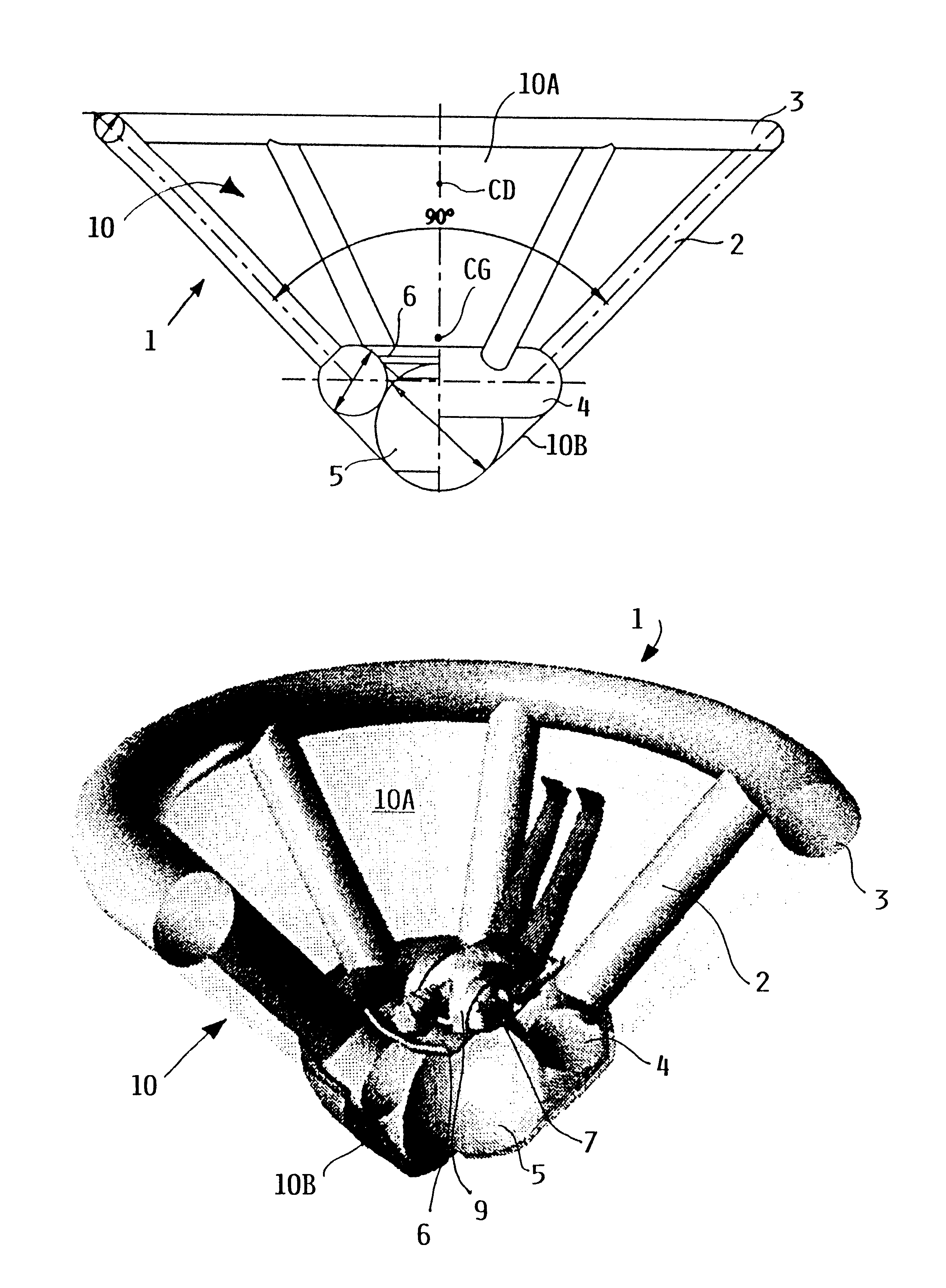
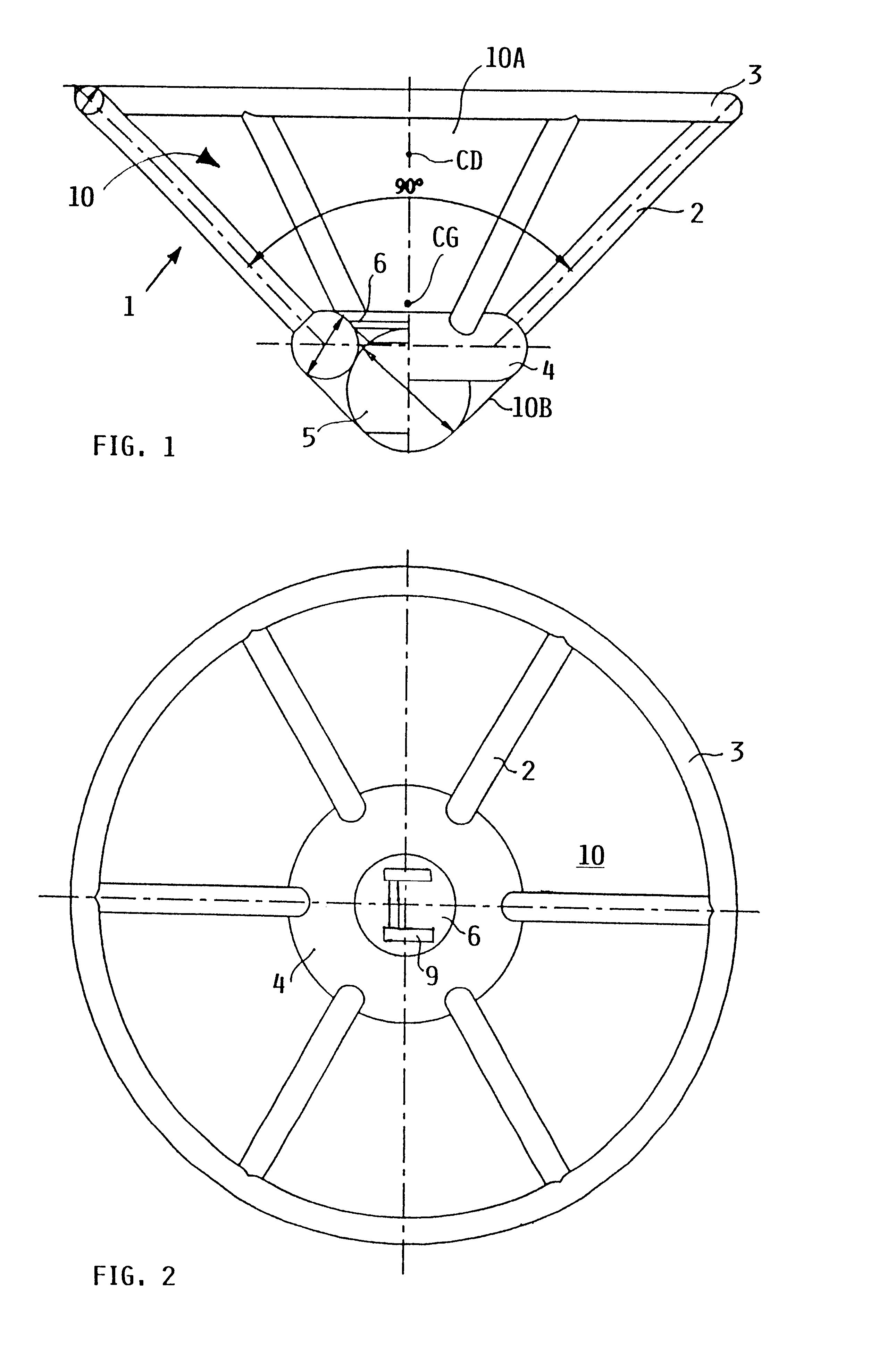
As shown in FIGS. 1 and 2, the apparatus according to the invention is an unfoldable, inflatable and thus deployable flying body 1 that has a generally conical shape, much like a badminton shuttlecock, in the inflated, deployed condition. The deployed flying body 1 is thus generally configured as a conical hollow body of which the generally conical outer surface is closed, while the flat planar base surface at the top thereof is open. The flying body 1 includes an inflatable spherical central airbag or pneumatic damping body 5, an inflatable lower inner stabilizing ring 4 secured to the damping body 5, an inflatable upper outer stabilizing ring 3, and plural (e.g. six) inflatable spoke struts 2 extending and interconnected between the inner lower stabilizing ring 4 and the outer upper stabilizing ring 3. Each of these elements, the pneumatic damping body 5, the stabilizing rings 3 and 4, and the spoke struts 2, are made of substantially gas-tight fabric and are selectively deflatab...

second embodiment

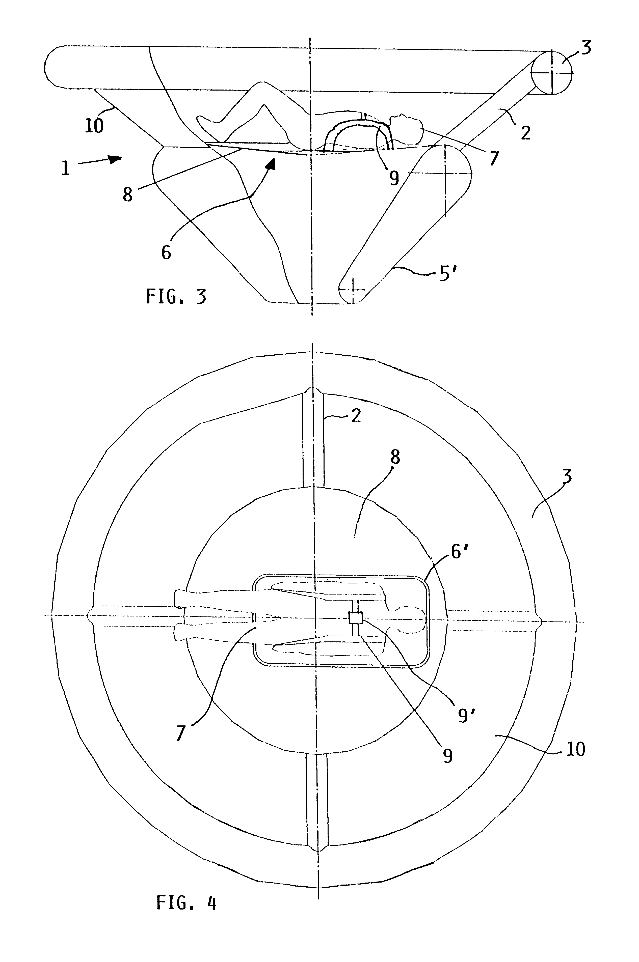
FIGS. 3 and 4 show the construction of the flying body 1. In general, the same reference numbers are used to designate the same or similar components in FIGS. 3 and 4 on the one hand, and in FIGS. 1 and 2 on the other hand. A redundant description of these components will not be provided. The primary difference between this embodiment of FIGS. 3 and 4 and the embodiment of FIGS. 1 and 2 relates to the nose structure of the conical flying body. In the embodiment of FIGS. 1 and 2, the nose structure includes the spherical pneumatic damping body 5 and the circular toroidal lower inner stabilizing ring 4. On the other hand, in the embodiment of FIGS. 3 and 4, the nose structure comprises a pneumatic damping body 5' in the form of a conically tapering ring body, e.g. in the manner of a funnel or cone with an inflatable sidewall.

This nose structure of FIGS. 3 and 4 omits a separate lower stabilizing ring 4, but the upper end of the conically tapering ring body 5' incorporates, forms or ac...


PUM


Abstract

A person can safely descend from a burning high-rise building or the like using an inflatable flying body that has a hollow conical form in an inflated deployed condition, but is deflated and folded into a backpack form in a stowed condition. The flying body includes an upper stabilizing ring, a lower nose structure with a pneumatic damping body, spoke struts extending conically therebetween, a cover skin covering the abovementioned inflatable components to form the conical outer surface and provide aerodynamic braking drag, and gas generators to inflate the inflatable components. A person straps on the apparatus in the stowed backpack form and pulls a handle to actuate the gas generators for inflating the apparatus, whereby the expanding apparatus ejects the person from the building and then orients itself in a nose-down attitude during the descent. The pneumatic damping body damps and dissipates the landing impact energy.

Description

The invention relates to a method and a system utilizing an inflatable flying body for rescuing a person from a great height in an emergency, for example in the event of a fire or the like in a high-rise building, a tower, or even an aircraft.BACKGROUND INFORMATIONIt has not been possible in practice to provide an automatic and self-contained rescue system for rescuing persons who are trapped in a dangerous situation at a great height, for example in a fire in a high-rise building, or even in an aircraft in an emergency situation. While it may be possible to use a typical parachute in some emergency situations, for enabling the endangered person to descend to the ground, it must be considered that the use of a parachute requires considerable instruction, training, and prior practice in order to ensure that a reliable and safe descent can be achieved. However, a method and system for rescuing persons from a great height in an emergency situation must be suitable for rescuing persons ...

Claims


Application Information

Patent Timeline
IPC IPC(8): B64D1/00B64D25/00B64D19/00B64D25/08B64D1/14A62B1/00A62B1/22
CPCB64D1/14B64D19/00B64D25/08A62B1/22
Inventor PICHKHADZE, KONSTANTINZAYTSEV, IGORWALTER, STEPHAN
Owner AIRBUS DEFENCE & SPACE
Learn More