On line monitor for a control device

a control device and monitor technology, applied in the direction of program control, electric programme control, instruments, etc., can solve the problems of inability to detect a clean transition from one logical state to another, adc's won't fit,

Inactive Publication Date: 2003-08-26
SQUARE D CO
View PDF8 Cites 89 Cited by
  • Summary
  • Abstract
  • Description
  • Claims
  • Application Information

AI Technical Summary

Problems solved by technology

Although the system would be more accurate because the entire analog system is located on a single board, the disadvantage and limiting factor is that the ADC's wont fit on the present packaging for the modular system DSP base in most applications.
Without hysteresis, it is often impossible to detect a clean transition from one logical state to another.

Method used


Image

  • On line monitor for a control device
  • On line monitor for a control device
  • On line monitor for a control device

Examples


Embodiment Construction

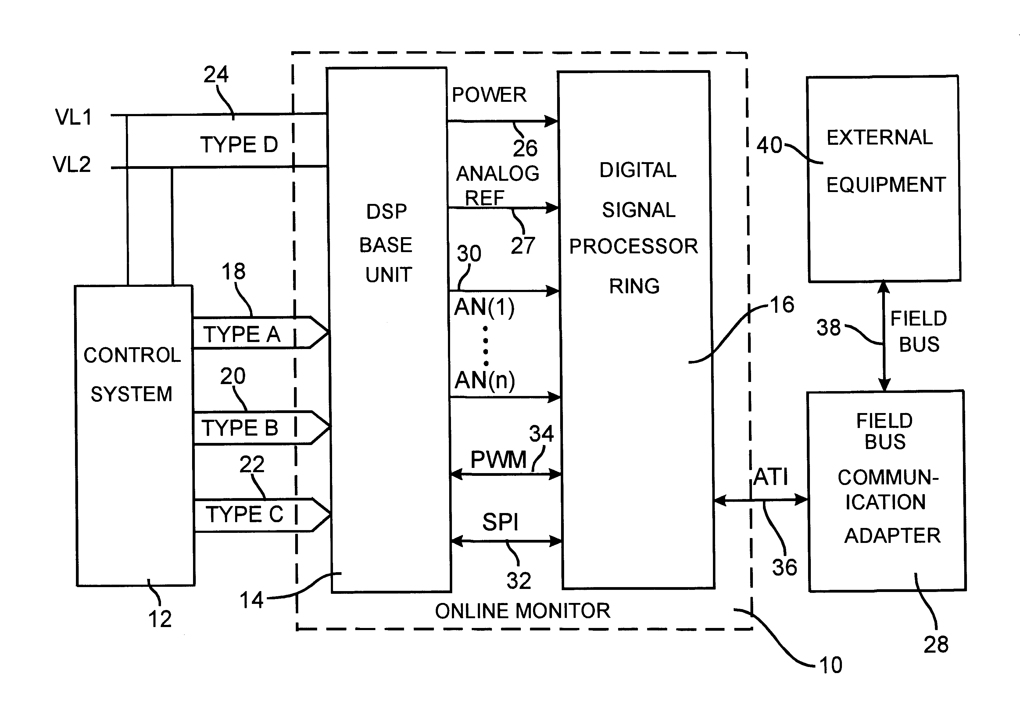
indicates to a user that the online monitor 10 is in the ON_LINE_MONITOR mode. The foreground task then waits for a new command to be received from the fieldbus 38, monitoring the battery while it waits. When a new command is received from the fieldbus 38, a parser routine is executed to interpret the command. The parser routine executed by the foreground task in the ON_LINE_MONITOR process is capable of interpreting commands and detecting if a command received is valid in the ON_LINE_MONITOR mode. Assuming it is, the parser can also determine if the parametric values contained in the command are valid, and can modify registers, read data, etc. as determined by the command. Once the command is parsed and the appropriate action taken, a response is built by the foreground task and sent back to external equipment 40 via the fieldbus 38. Once this response has been built, the ON_LINE_MONITOR process is complete. There are no time restrictions placed on the time between commands which i...


PUM


Abstract

An online monitor that can be permanently attached to a device to be monitored continuously monitors a set of analog signals and initiates data capture over a window of time when a user programmable set of conditions is satisfied. The online monitor includes a digital signal processing unit, a modular, interchangeable, analog signal conditioning base unit that can be tailored to the specific requirements of the process to be monitored and a modular, interchangeable, communication interface unit. The interface unit permits the digital signal processing unit to exchange data with external equipment such as network computers via a number of industry standard communication fieldbus protocols. The online monitor provides the capability to define the trigger condition under which data capture is initiated by comparing a user defined signal to a function of the instantaneous value of another signal or constant. Data captured is stored indefinitely in internally battery backed memory and the instant at which data capture is initiated is determined accurately via a time tagging function, so the data can be retrieved at a later time.

Description

Applicants' invention relates generally to the field of control systems and more particularly to an online monitor used to continuously check various data points in a control circuit and record the data when an event occurs.Chart recorders and oscilloscopes have been available for many years for use as portable test equipment to examine analog, time varying signals over short intervals. Typically, these devices reside in a laboratory or when they are taken into the field, they are hand carried by an individual responsible for troubleshooting equipment, or to examine analog signals of interest. Rarely is such equipment left attached to a piece of equipment to be monitored in the field for long periods of time, for several reasons. Such equipment is typically expensive and often not suited for an industrial environment in which the electrical and ambient conditions are hostile. Conventional chart recorders and oscilloscopes are generally not designed to capture data for long periods o...

Claims


Application Information

Patent Timeline
Patent Type & Authority Patents(United States)
IPC IPC(8): G05B19/04G05B19/042G05B23/02
CPCG05B19/0428G05B23/0221
Inventor BUDA, PAUL ROBERTDEW, LARRY ALANWHEATON, TODD CHARLESWINN, JACKIE LAVERNE
Owner SQUARE D CO
Why Eureka
Try Eureka