Bistatic radar system using transmitters in mid-earth orbit

a radar system and transmitter technology, applied in the field of radar systems, can solve the problems of limited operational flexibility, large illumination intensity of the target, and significant constraints on the system, and achieve the effect of sufficiently large illumination intensity for detection

Inactive Publication Date: 2003-09-02
RAYTHEON CO
View PDF10 Cites 22 Cited by
  • Summary
  • Abstract
  • Description
  • Claims
  • Application Information

AI Technical Summary

Problems solved by technology

Unfortunately, the requirement that velocity vectors lie within the bistatic plane imposes significant constraints on the system and limits the operational flexibility.
A further limitation of conventional radar systems is that, in order to reach long ranges the beam must be narrow (i.e., the antenna gain must be high) so that the intensity of illumination falling on the target is sufficiently large for detection.
In addition, when the ground is being illuminated from the air, long range observations result in a very shallow angle of illumination.
Thus, much of the energy in the beam is wasted because it does not re...

Method used


Image

  • Bistatic radar system using transmitters in mid-earth orbit
  • Bistatic radar system using transmitters in mid-earth orbit
  • Bistatic radar system using transmitters in mid-earth orbit

Examples


Embodiment Construction

While the present invention is described herein with reference to illustrative embodiments for particular applications, it should be understood that the invention is not limited thereto. Those having ordinary skill in the art and access to the teachings provided herein will recognize additional modifications, applications, and embodiments within the scope thereof and additional fields in which the present invention would be of significant utility.

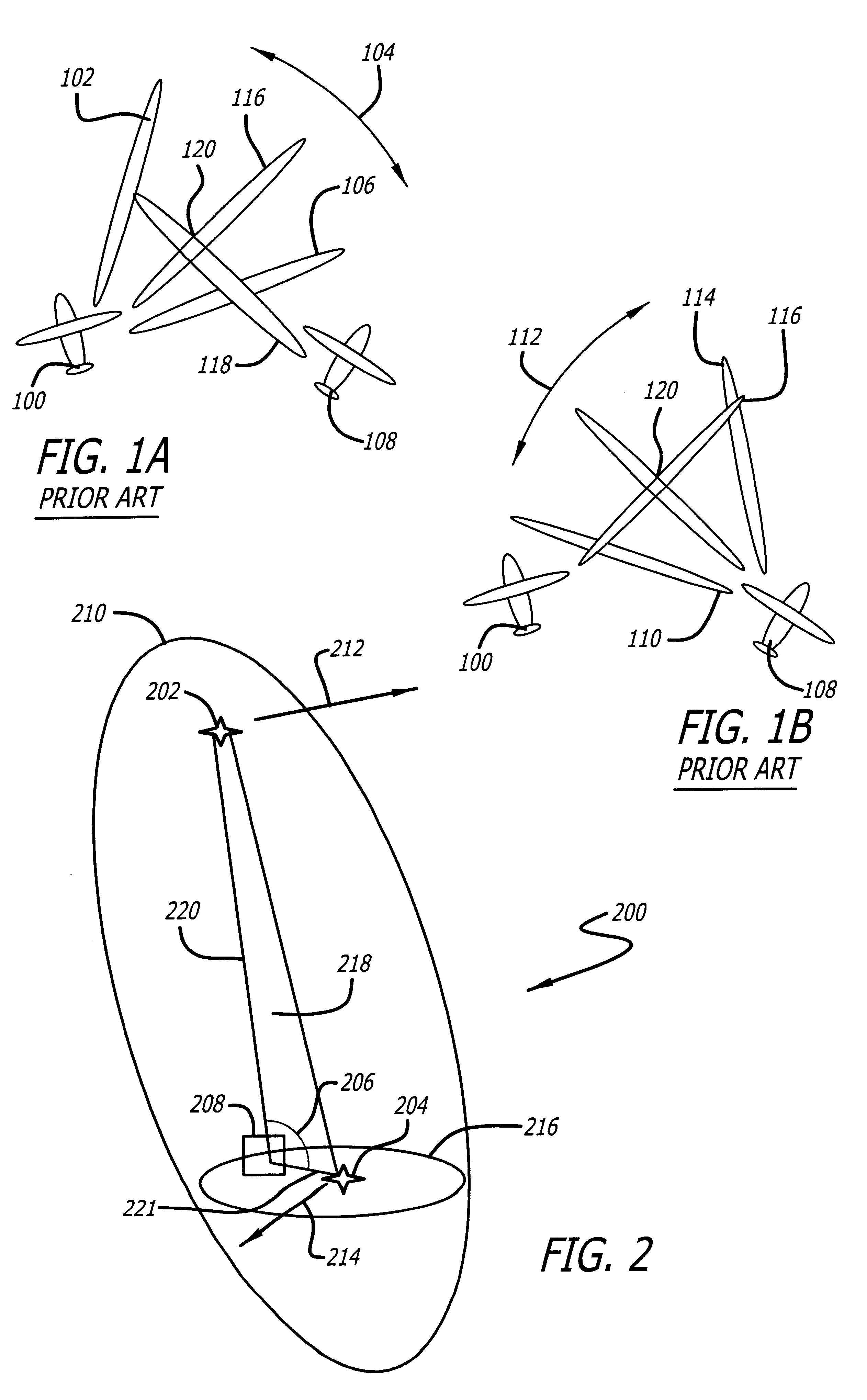
FIG. 2 is an illustrative embodiment of a bistatic radar architecture 200 implemented in accordance with the teachings of the present invention. In FIG. 2, a transmitter 202 and a receiver 204 are shown. In the illustrative embodiment, the transmitter 202 is located at Middle Earth Orbit (MEO); however, the transmitter may be located anywhere between Lower Earth Orbit (LEO) and Geo-synchronous Orbit (GEO). In the present embodiment, the selection of useful orbits depends on (approximately) matching the velocity-to-range ratio (V.sub.T / R.su...


PUM


Abstract

A bistatic radar system and method. In the illustrative embodiment, a receiver is positioned in a horizontal plane. A transmitter is then positioned in Middle Earth Orbit at a position that is nearly vertical to the plane of the receiver. This configuration provides significant flexibility for the radar system. As such, the radar system may engage in flight patterns, in which the transmitter and receiver have velocity vectors in opposite directions (GMTI mode), the same direction (SAR mode) and variations in between (mixed mode). Lastly, a broad beam is generated from the transmitter and illuminates an area enabling several receivers to simultaneously observe the illuminated area.

Description

1. Field of the InventionThis invention relates to radar systems. Specifically, the present invention relates to bistatic radar systems.2. Description of the Related ArtIn a mono-static radar system, the transmitter and the receiver are co-located. In a bistatic radar architecture, the transmitter and receiver are substantially separated. In addition, both the transmitter and the receiver may be mounted on either fixed or moving platforms. Bistatic radar is therefore distinguished from monostatic radar where the transmitter and receiver are mounted on the same platform and move together.A characteristic feature of bistatic radar systems is that the transmitter, the receiver and the target, form an iso-range ellipsoid with the transmitter and receiver at the foci of the ellipsoid. In addition, the transmitter, the receiver and the target define the bistatic plane.Further, the receiver, the target and the receiver's motion relative to the target instantaneously define a plane, known a...

Claims


Application Information

Patent Timeline
IPC IPC(8): G01S13/90G01S13/00
CPCG01S13/003G01S13/90G01S2013/9058G01S13/9058G01S13/9029
Inventor MOORE, KENNETH L.RICHARDS, CHESTER L.CHEN, PILEIH
Owner RAYTHEON CO
Why Eureka
Try Eureka