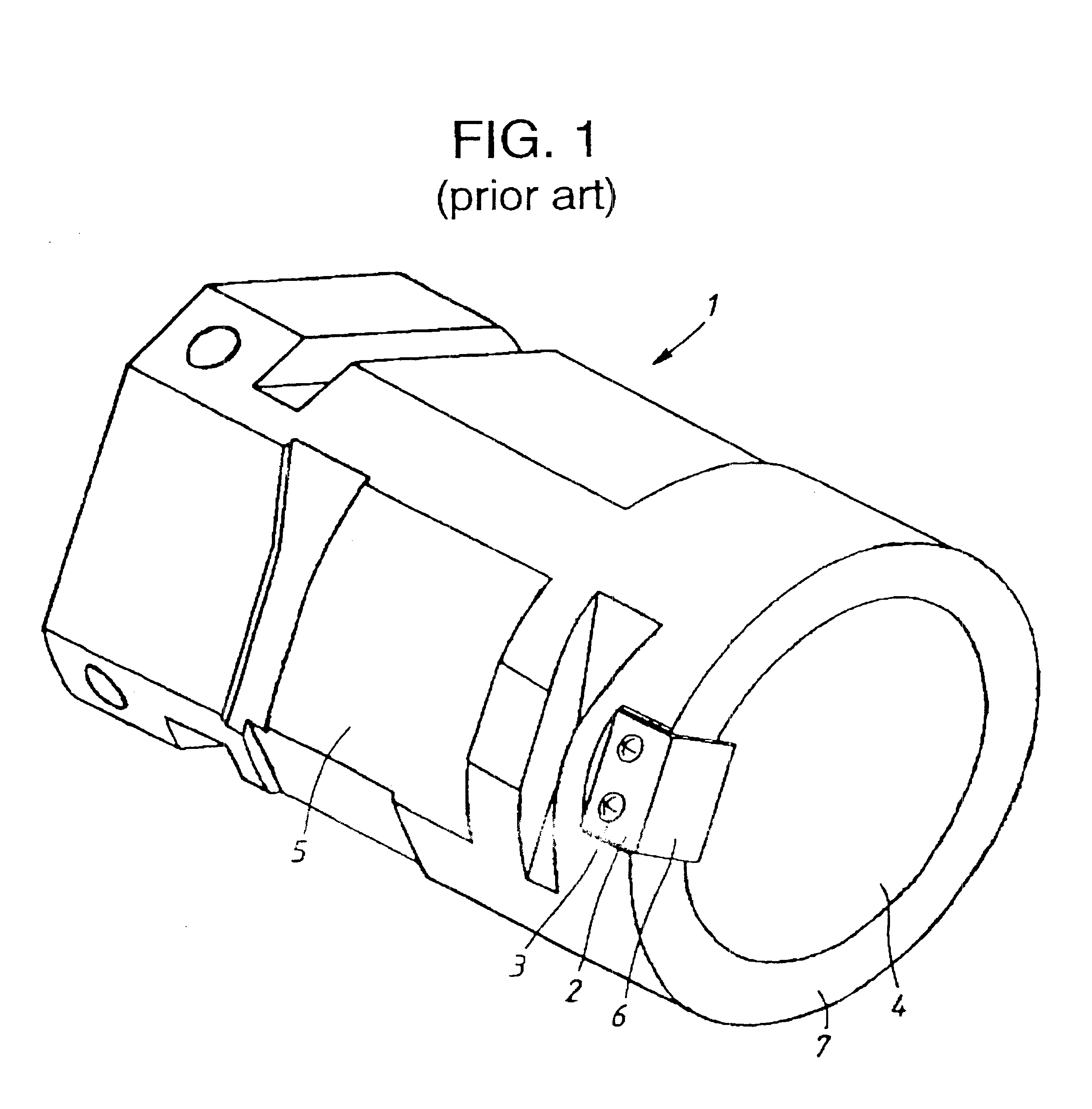
Tool pot for tool magazine
a tool magazine and tool pot technology, applied in the field of tool pots for tool magazines, can solve the problems of inability to reduce the weight of the tool pot 1 sufficiently, and achieve the effect of reducing the weight of the tool pot 1
- Summary
- Abstract
- Description
- Claims
- Application Information
AI Technical Summary
Benefits of technology
Problems solved by technology
Method used
Image


Examples
Embodiment Construction
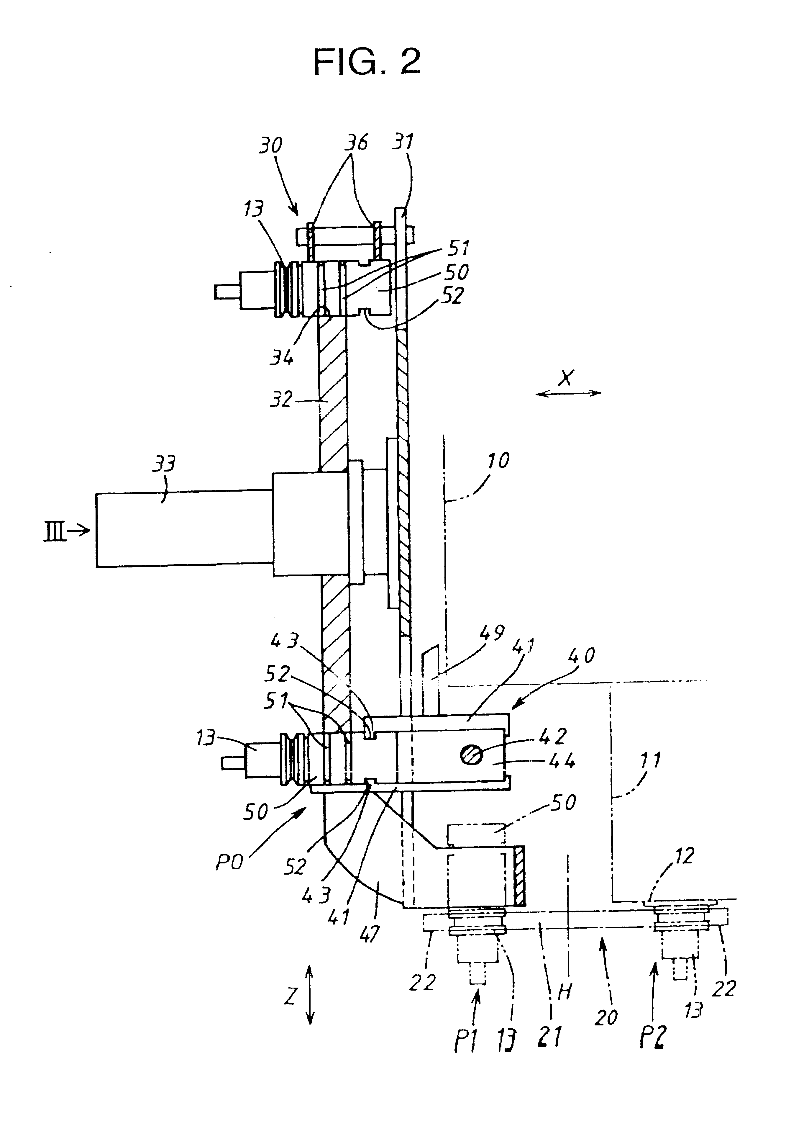
A tool magazine attachment equipped with a tool pot according to the invention will be described with reference to FIGS. 2, 3. In FIG. 2, a column 10 is guided and supported on a bed (not shown) such that the column 10 can slide in a direction of an X-axis by a servo motor (not shown). In exchanging tools, the column 10 is moved to a tool exchanging portion P2 shown in FIG. 2. A spindle head 11 is vertically slidably guided and supported on a front face of the column 10. The spindle head 11 is moved by a servo motor (not shown) in a vertical direction.
A spindle 12 is rotatably supported by the spindle head 11 around an axis parallel to the Z-axis and rotationally driven by a spindle motor (not shown). A tool 13 is removably fitted to a tip of the spindle 12. The tool 13 is constructed of a tool holder to which a cutting tool such as a drill is fitted. An automatic tool changer (hereinafter "ATC") 20 is installed on the bed between the column 10 positioned at the tool exchanging posi...
PUM
 Abstract
Description
Claims
Application Information