
Apparatus for connecting transmissions paths

a transmission path and apparatus technology, applied in electrical apparatus, waveguide devices, waveguide types, etc., can solve problems such as unwanted transmission losses, and achieve the effects of low vswr, good mechanical connection, and simple and economical manufacturing

Inactive Publication Date: 2003-09-16
TELEFON AB LM ERICSSON (PUBL)
View PDF5 Cites 6 Cited by
  • Summary
  • Abstract
  • Description
  • Claims
  • Application Information

AI Technical Summary

Benefits of technology

An advantage of the present invention is that a connection that has a relatively low VSWR (voltage standing wave ratio) over a wide range of frequencies, especially at microwave frequencies, between a stripline circuit and a coaxial conductor can be obtained.
is that a connection that has a relatively low VSWR (voltage standing wave ratio) over a wide range of frequencies, especially at microwave frequencies, between a stripline circuit and a coaxial conductor can be obtained.
Another advantage is that a good mechanical connection between the coaxial connector and the stripline circuit can be attained.
Still another advantage of the present invention is that proper alignment can be obtained of the coaxial connector and the conductive elements to which existing stripline circuit can be readily adapted, and which is simple and economical to manufacture.

Problems solved by technology

Otherwise unwanted transmission losses, reflections and other undesirable characteristics can result.
Other problems include facilitating mounting of a coaxial cable connector to a flexible stripline circuit, and improving mechanically the connection between the coaxial connector and the stripline circuit.

Method used


Image

  • Apparatus for connecting transmissions paths
  • Apparatus for connecting transmissions paths
  • Apparatus for connecting transmissions paths

Examples


Embodiment Construction

Turning now to the drawings, a coaxial cable connector is illustrated as coupling high frequency signals between a coaxial connector and an end device. It should be understood from the outset that the coaxial connector is shown in its most simple form, i.e., with one end device and one coaxial connector. However, it should be understood that the teachings of this invention are applicable to a future end device, which would accommodate a much larger number of connections. In addition, the specifically disclosed male / female positions can be reversed if desired.

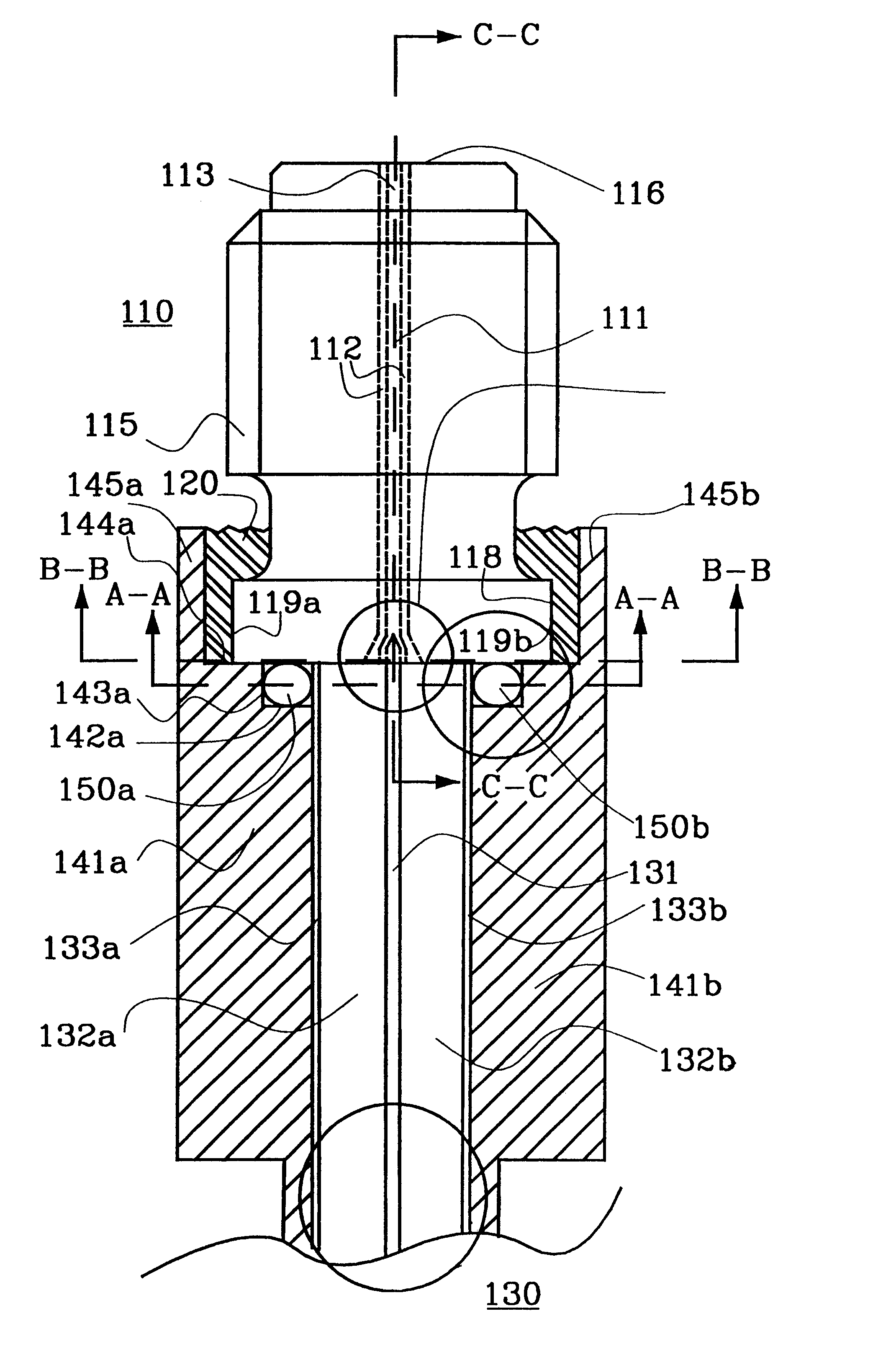
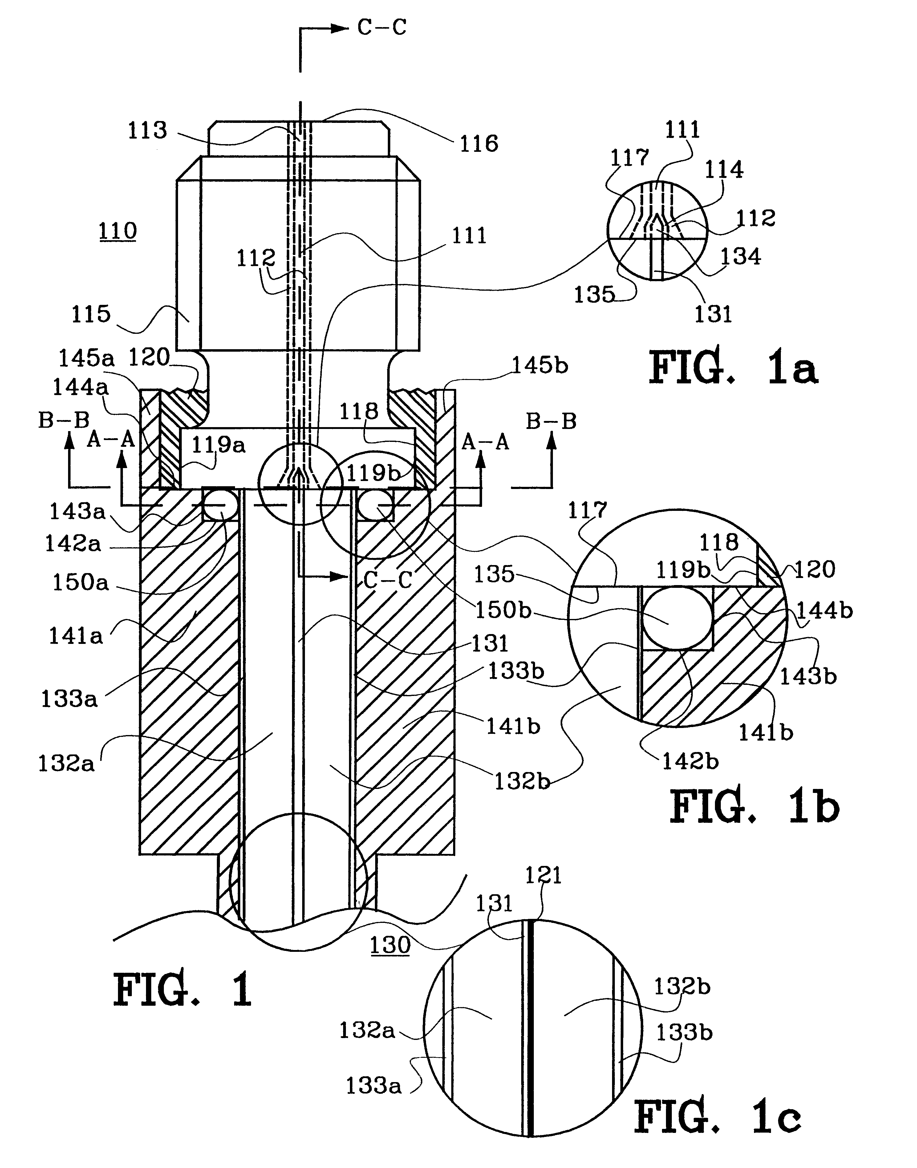
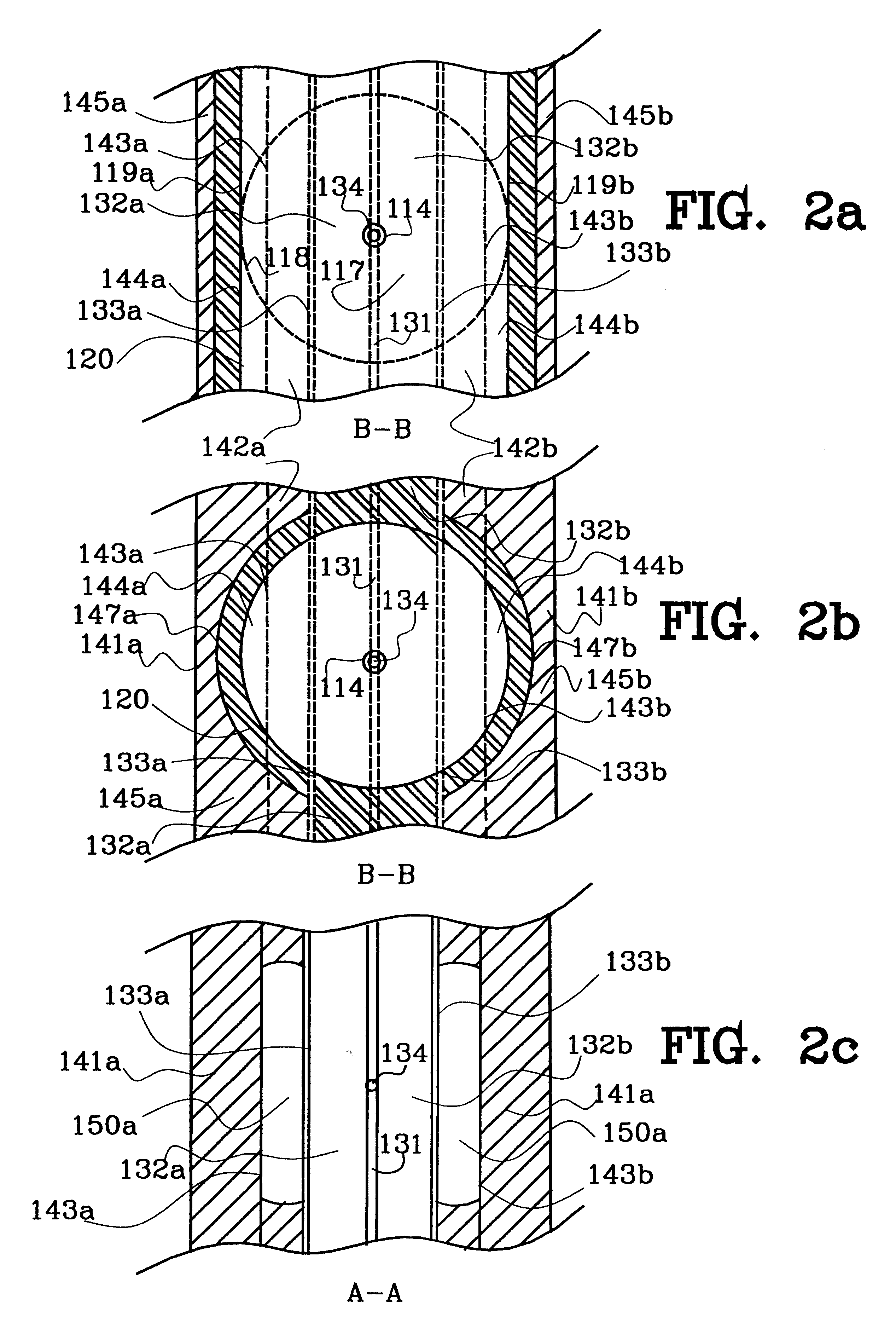
Coaxial cable includes a conventional male end connector, which includes a shielded male pin extending therefrom. The male coaxial connector mates with a conventional female connector that is attached to a stripline circuit. As perhaps shown best in FIG. 1 a housing 110 of a female coaxial connector including one end part 117 with a planar end wall and opposite a protruding part 116 that mates with the male coaxial connector. Th...


PUM


Abstract

The present invention relates generally to an apparatus for interconnecting coaxial connectors with stripline circuits. A general coaxial connector housing is by glue fixed adjacent to the stripline circuit and at least one conductive element is placed in between the connector housing and the stripline ground planes.

Description

The present invention generally concerns a connector for connecting transmissions paths. Specifically, the present invention relates to an apparatus for interconnecting coaxial connectors with stripline circuits.DESCRIPTION OF RELATED ARTIt is well known that special precautions must be taken when dealing with signal transmission circuits in the radio to microwave frequency range. Otherwise unwanted transmission losses, reflections and other undesirable characteristics can result. Microwave signals are often carried on shielded coaxial cables. These cables are typically used to transmit microwave signals to and from various end devices. Many of these end devices require that connections to them are made by way of flat or "stripline" conductors residing on a surface of a dielectric board (hereinafter "a stripline circuit"). Examples of such devices include power splitters, mixers, hybrid couplers, directional couplers, filters, attenuators, phase shifters, antenna elements and antenn...

Claims


Application Information

Patent Timeline
Patent Type & Authority Patents(United States)
IPC IPC(8): H01P5/08
CPCH01P5/085H01R9/0515
Inventor DRACKNER, PETER NILSSONRIVAS, PATRIKSTRANDBERG, ULRIKA
Owner TELEFON AB LM ERICSSON (PUBL)
Learn More